CD 617 ISSUE 1 : 27/07/2020
17. SOFTWARE SLOWING LIMITS (Using Cedes Dual Positioning System):
A. Almega2 Parameters
Note: When non-profile setup (Hydraulic), only the parameters underlined and in BOLD apply.
a. POSITIONING SYSTEM (Press MENU->POSITIONING SYSTEM PARAMETERS)
i. SOFTWARE SLOW LIMITS = YES
ii. SLOW LIMIT DECEL RATE = 1700
iii. SLOW LIMIT JERK RATE = 1700
iv. CALC SLOW LIMIT DIST HS = ( READ ONLY)
v. SLOW LIMIT RESET DIST = 750
vi. SLOW LIMIT DIST ADJUST = -50
b. TRAVEL SPEEDS (Press MENU->PARAMETERS->TRAVEL SPEEDS)
i. SLOW LIMIT COMMS LOST SPEED = 0.5 m/s
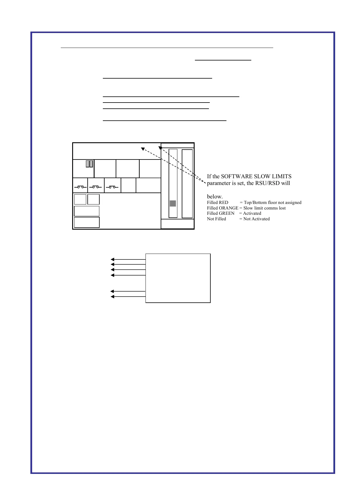
B. RSU and RSD status with software slowing limits.
a. Ensure Bottom and Top floors are assigned.
C. Wiring
a. Ensure CEDES channel 1 connected to Position Encoder CAN
b. Ensure CEDES channel 2 connected to CAR CAN
D. Calculated Slowing Limit Distance HS
This can be viewed from the parameter (POSITIONING SYSTEM PARAMETERS->CALC SLOW LIMIT DIST
HS). This parameter is updated every 1s for the speed HS. It's also updated when running with the HS value.
E. Non-profile setup
a. When using non profile control and slow dist calc=Travel Speed PAR, i.e. hydraulic, adjust the
backup slowing limit by setting the ‘SLOW LIMIT DIST ADJUST’ by x value.
e.g. when it is set to default -50, it puts the backup slowing limits -50mm behind the actual slowing
distance. (Press MENU->POSITIONING SYSTEM PARAMETERS-> SLOW LIMIT DIST ADJUST)
b. The debug screen will show the last up/down slow distance.
(Press MENU->POSITIONING SYSTEM INFO-> DEBUG INFO)
C1 H (Grey)
GND (Green)
+24 V (White)
GND (Black)
+24V (Pink)
C2L (Brown)
If the SOFTWARE SLOW LIMITS
parameter is set, the RSU/RSD will
indicate the software slow limit status as
below.
Filled RED = Top/Bottom floor not assigned
Filled ORANGE = Slow limit comms lost
Filled GREEN = Activated
Not Filled = Not Activated
 Loading...