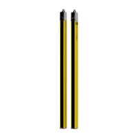
What to do if Leuze Lighting Equipment shows short circuit against +24 V at OSSD1?
- TTraci BoydSep 2, 2025
If there is a short circuit against +24 V at OSSD1 in your Leuze Lighting Equipment, check the wiring and replace the cable if necessary.

What to do if Leuze Lighting Equipment shows short circuit against +24 V at OSSD1?
If there is a short circuit against +24 V at OSSD1 in your Leuze Lighting Equipment, check the wiring and replace the cable if necessary.
What to do if Leuze Lighting Equipment shows short circuit against +24 V at OSSD2?
If there is a short circuit against +24 V at OSSD2 in your Leuze Lighting Equipment, check the wiring and replace the cable if necessary.
What to do if Leuze Lighting Equipment TH signal dropped out before protective field was cleared again during override?
| Type | Safety Light Curtain |
|---|---|
| Protected Field Height | 300 mm |
| Number of Beams | 2 |
| Operating Voltage | 24 V DC |
| Response Time | 9 ms |
| Resolution | 14 mm, 30 mm |
| Output Type | OSSD |
| Connection Type | M12 connector |
| Protection Class | IP65 |
| Outputs | 2 safety outputs OSSD |
| Connection | M12 connector |
| Protection Rating | IP65 |
| Standards | EN/IEC 61496-1 |
Defines the proper application and potential misuse scenarios for the safety sensor.
Specifies the qualifications and expertise required for handling the safety sensor.
Explains the fundamental concept and operational logic of Smart Process Gating.
Details the various operating modes available for SPG functionality.
Provides instructions and considerations for the physical installation of the safety sensor.
Details the necessary steps and pin assignments for connecting the safety sensor.
Guides on the initial power-up procedure and readiness checks for the sensor.
Explains the process of correctly aligning the transmitter and receiver.
Outlines essential checks before initial startup and after system changes.
Defines the roles and responsibilities of manufacturers and operators regarding safety.
Specifies conditions under which the manufacturer's liability is excluded.
Provides an overview of different MLC models and their features.
Explains the function of LEDs and the 7-segment display for status indication.
Introduces Smart Process Gating and its core operational principles.
Lists the prerequisites and conditions for implementing Smart Process Gating.
Explains the function and usage of the start/restart interlock mechanism.
Details how the blanking function operates and its applications.
Describes typical applications of SPG for safeguarding access points.
Guidance on the proper positioning and arrangement of sensor components.
Provides detailed pinout information for connecting the transmitter and receiver.
Configuration details for Operating Mode 1 with qualified stop function.
Step-by-step instructions for powering up the safety sensor.
Procedure for correct alignment of the transmitter and receiver.
Explanation of the acknowledgement button's role in unlocking safety functions.
Checklist for integrators before initial startup and after modifications.
Guidance for regular operational checks performed by end-users.
Instructions for cleaning and maintaining the safety sensor's components.
Information on diagnosing and resolving faults using LED and display indicators.
Contact information for technical assistance, service, and repairs.
Overview of key technical data, including protective field and safety parameters.
Provides physical dimensions and weight details for the device.
Information on part numbers, nomenclature, and available accessories.