IFP-0503 Page 4
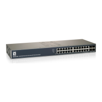
LED Status
PWR 1, 2
ON Power On
OFF Power Off
SW (relay)
ON both PW1 and PW2 are connected
OFF only PW1 or PW2 is connected
LNK(1 ~ 4)
ON TX link is detected
OFF TX port is not detected
Flashing TX port is active
POE(1 ~ 4)
ON PD is connected
OFF No PD is connected
F5
ON FX fiber is detected
OFF FX fiber is not detected
Flashing FX fiber is active
IFP-0503 Page 5
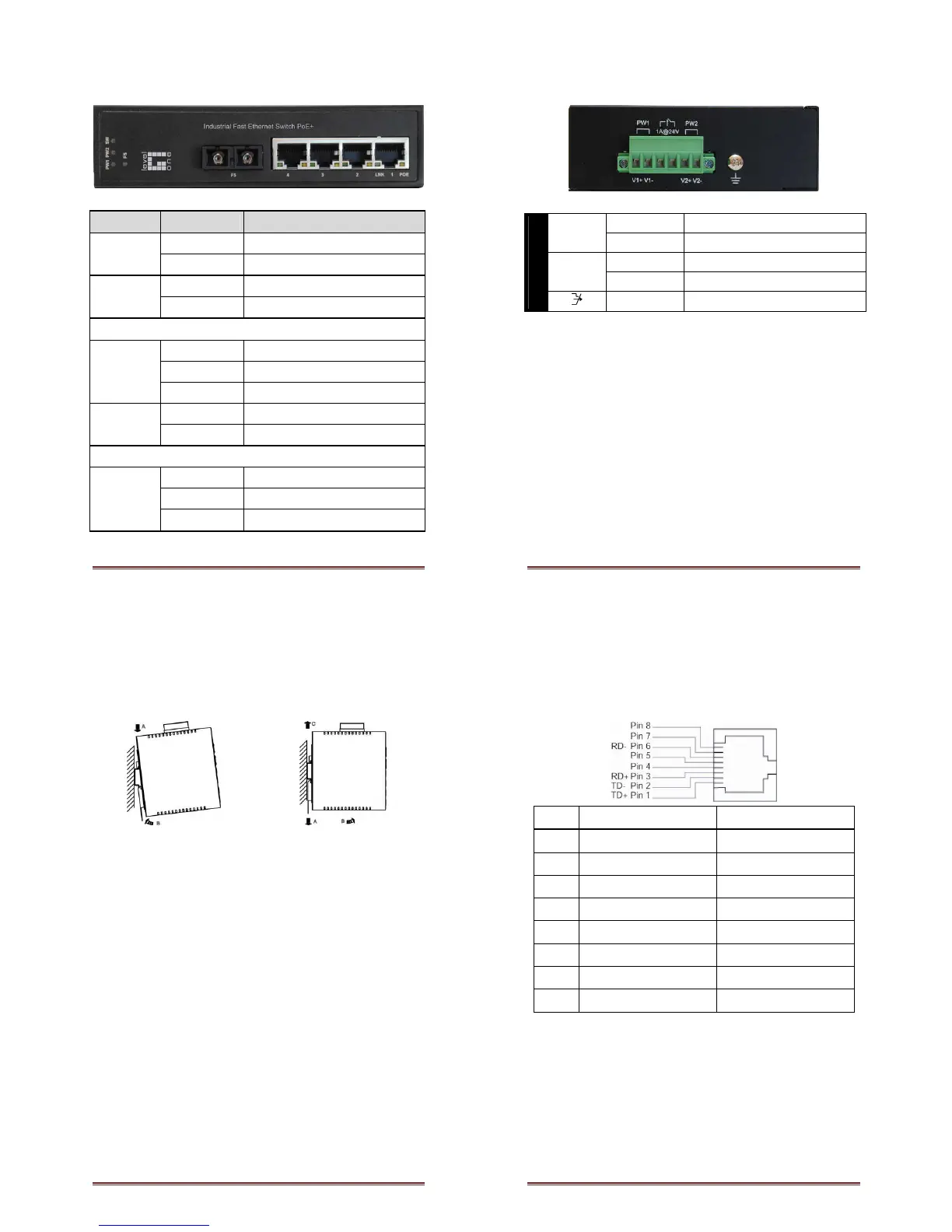
Power Ground
Relay Output
1A @ 24VDC
IFP-0503 Page 6
DIN Rail Mount
• Assembly: Place the switch on the DIN rail from above using
the slot. Push the front of the switch toward the mounting
surface until it audibly snaps into place
• Start-up: Connect the supply voltage to start up the switch
via the terminal block (or DC JACK)
• Dismantling: Pull out the lower edge and then remove the
switch from the DIN rail.
IFP-0503 Page 7
10/100Base-TX Connector
The following lists the pin-out of 10/100Base-TX ports.
1 Output Transmit Data + Input Receive Data +
2 Output Transmit Data - Input Receive Data -
3 Input Receive Data + Output Transmit Data +
4 NC NC
5 NC NC
6 Input Receive Data - Output Transmit Data -
7 NC NC
8 NC NC