WARNINGS AND CAUTIONS:
• TO AVOID FIRE, SHOCK, OR DEATH; TURN OFF POWER AT CIRCUIT BREAKER OR FUSE AND TEST THAT THE POWER IS OFF BEFORE WIRING!
• Tobeinstalledand/orusedinaccordancewithelectricalcodesandregulations.
• Toavoidoverheatingandpossibledamagetothisdeviceandotherequipment,DO NOTinstalltocontrolareceptacle,amotor,oratransformer-operatedappliance
otherthanapplicablespeciedlightingload:IncandescentandLED.
• Whenusingina3-wayapplicationuseonesensorandonestandard3-wayswitch.Cannotbeusedwithanothersensor,orina4-wayapplication.
WARNINGS AND CAUTIONS:
• Ifyouarenotsureaboutanypartoftheseinstructions,consultanelectrician.
• Cleanoutersurfacegentlywithdampclothonly.DO NOT usesoapsorcleaningliquids.
• Nouserserviceablecomponents.DO NOT attempttoserviceorrepair.
• UsethisdeviceWITH COPPER OR COPPER CLAD WIRE ONLY.
Push down tabs per
diagram, one at a time and
rotate forward to release
1 2
0 3
1 2
0 3
Attach new face by inserting
bottom hinge tabs, then pivot
and snap the color kit to attach
TOOLS NEEDED TO INSTALL YOUR DEVICE
Slotted/PhillipsScrewdriver ElectricalTape Pliers
Pencil Cutters Ruler
Changing the color of your device:
Yourdevicemayincludecoloroptions.Tochangecolorofthe
faceproceedasfollows:
BK
RD
3-Way
Terminal
Screw marked
Red (RD)
2
Terminal
Screw marked
Black (BK)
Brass
Terminal Screw
Marked 3-Way
Terminal Label:
Use Terminal for 3-Way Applications Only.
For Single Pole Applications, Do Not Remove This Label.
4
1
3
Ground
(Green Screw)
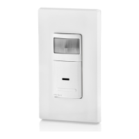
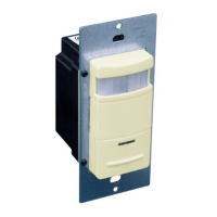
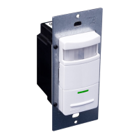
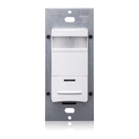
Sensor
Single Pole and 3-Way Wide View Motion Activated Light Control
Cat. No. IPS06, IPV06 - INDOOR USE ONLY
Ratings:120VAC,60Hz600WIncandescent&150WLED
INSTALLATION INSTRUCTIONS
PK-93978-10-00-2A
FEATURES
• Cat.No.IPS06andIPV06haveasensingareaofcoverageof
30ft.x30ft.,andasensingangleof180
O
(see Sensing Area
Coverage figure on page 2).
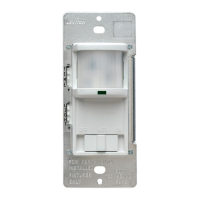
• Adjustablelightandtime-delaycontrolsarelocatedonthefront
ofthedevice(See adjustment setting section on page 2
for details).
• LEDindicatorisusedtoalerttheuserofthestatusofthedevice.
• AdjustableTimeDelaysettingfor30seconds,5min,15min
&30min.
• Occupancysensorcanbeconvertedtoavacancysensor
(See adjustment settings on page 2).
LOCATION / MOUNTING
Thedevicerespondstotemperaturechangesandcareshouldbe
takenwhenmountingthedevice.DO NOTmountdirectlyabove
aheatsource,inalocationwherehotorcolddraftswillblow
directlyonthesensor,orwhereunintendedmotion(e.g.,hallway
trafc)willbewithinsensor’seld-of-view.
Sensor is located in electrical box with LINE
connection:
C
Hot (Black)
Neutral (White)
BK
LOAD
Line
120VAC
60 Hz
Green
Ground
3-Way/
Brass
Common Terminal
(Black Screw)
Pigtail
Pigtail
Green
Ground
RD
First Traveler
Second Traveler
Hot (Black)
Neutral (White)
BK
LOAD
Line
120VAC
60 Hz
Sensor
Green
Ground
Green
Ground
3-Way/
Brass
Common Terminal
(Black Screw)
Pigtail
Pigtail
First Traveler
Second Traveler
RD
BK
RD
3-Way
2
2
1
3
5
Common
Terminal
(Black
Screw)
Ground
(Green Screw)
1
4
4
3
5
Common
Terminal
(Black
Screw)
Ground
(Green Screw)
BK
RD
3-Way
2
3
5
1
4
3-Way Switch
2
1
5
4
3
B
Sensor is located in electrical box with LOAD
connection:
WIRING SWITCH:
Connect wires per WIRING DIAGRAM as follows:
• GreenorbarecopperwireinwallboxtoGreenterminalscrew.
• OnepigtailwiretotheBlackscrewterminalmarked"COM"and
onepigtailwiretotheBrassterminal(same side of switch).
• Connectthefollowing4wiresusinganappropriatelysized
wirenut:
1. Common/Linewire(identified in step 2).
2. SecondTravelerwire(note color from step 2).
3. Twopigtailwiresfromthe3-wayswitch.
• FirstTravelerwallboxwire(note color from step 2)to
Brassscrewterminalontheswitch(opposite side from the
Black screw).
WIRING SENSOR:
Connect wires per WIRING DIAGRAM as follows:
• GreenorbarecopperwireinwallboxtoGreenterminalscrew.
• Common/Loadwallboxwireidentiedwhenremovingold
switch(step 2)toterminalscrewmarked"BK".
• FirstTravelerwallboxwire(note color from step 2)toterminal
screwmarked"3-way".
• SecondTravelerwallboxwire(note color from step 2)to
terminalscrewmarked"RD".ThisTravelerfromtheswitchmust
gototheterminalscrewonthesensormarked"RD".
WIRING SENSOR:
Connect wires per WIRING DIAGRAM as follows:
• GreenorbarecopperwireinwallboxtoGreenterminalscrew.
• Common/Linewallboxwireidentiedwhenremovingoldswitch
(step 2)toterminalscrewmarked"BK".
• FirstTravelerwallboxwire(note color from step 2)toterminal
screwmarked"RD".
• SecondTravelerwallboxwire(note color from step 2)to
terminalscrewmarked"3-way".
WIRING SWITCH:
Connect wires per WIRING DIAGRAM as follows:
• GreenorbarecopperwireinwallboxtoGreenterminalscrew.
• OnepigtailwiretotheBlackscrewterminalmarked"COM"and
aonepigtailwiretothebrassterminal(samesideofswitch)
• Connectthefollowing4wiresusinganappropriatelysized
wirenut:
1. Common/Loadwire(identified in step 2).
2. FirstTravelerwire(note color from step 2).
3. Twopigtailwiresfromthe3-Wayswitch.
• SecondTravelerwallboxwire(note color from step 2)to
Brassscrewterminalontheswitch(opposite side from the
Black screw).
IMPORTANT:For3-wayapplications,notethatoneofthescrew
terminalsfromtheoldswitchbeingremovedwillusuallybea
differentcolor(Black)orlabeledCommon.Tagthatwirewith
electricaltapeandidentifyasthecommon(LineorLoad)inboththe
sensorwallboxandremotewallbox.
3-Way
1. LineorLoad (See important
instruction below)
2. Neutral
3. Ground
4. FirstTraveler–notecolor
5. SecondTraveler–notecolor
Single-Pole
1. Line(Hot)
2. Neutral
3. Ground
4. Load
Step 2
Identifying your wiring application
(most common):
NOTE:Ifthewiringinthewallboxdoesnotresembleany
ofthesecongurations,consultanelectrician.
Preparing and connecting wires:
Thisdevicecanbewiredusingsidewireterminal
screws.Chooseappropriatewirestripping
specicationsaccordingly.
• Makesurethattheendsofthewiresfromthewallboxarestraight
(cut if necessary).
• Removeinsulationfromeachwireinthewallboxasshown.
• For Single Pole Application, go to Step 4A.
• For 3-Way Application with the sensor on the Load side, go to Step 4B.
• For 3-Way Application with the sensor on the Line side, go to Step 4C.
Strip Gage
(measure bare wire
here or use gage on
back of the sensor)
5/8”
(1.6 cm)
Side Wire Connection
Sidewireterminalsaccept#14-12
AWGsolid copper wire only.
Step 3
Back Wire
Connection
Backwireopeningsuse#14-12
AWGsolid copper wire only.
BK
√
INSTALLING YOUR DEVICE
NOTE: UsecheckboxeswhenStepsarecompleted.
ONOFF
ONOFF
ONOFF
ONOFF
ONOFF
ONOFF
ONOFFONOFF
ONOFF
ONOFF
ONOFF
ONOFF
Step 1
WARNING:TO AVOID FIRE, SHOCK, OR
DEATH; TURN OFF POWERatcircuitbreakeror
fuseandtestthatpowerisoffbeforewiring!
WIRING SENSOR:
Connect wires per WIRING DIAGRAM as follows:
• GreenorbarecopperwireinwallboxtoGreenterminalscrew.
• LineHotwallboxwiretoterminalscrewmarked"BK".
• Loadwallboxwiretoterminalscrewmarked"RD".
• Terminalscrewmarked"3-way"shouldhaveRedinsulationlabel
afxed.
NOTE: Ifinsulatinglabelisnotafxedtoterminalscrewmarked
"3-way",useelectricaltapetocover.
• ProceedtoStep5.
Use Terminal for 3-Way
Applications Only.
For Single Pole Applications,
Do Not Remove This Label.
Hot (Black)
Neutral (White)
RD
Black
BK
White
LOAD
Line
120VAC, 60 Hz
Green
Ground
3-Way
(Brass
Screw)
Step 4
Single Pole Wiring Application:
A
3-Way Wiring with 3-Way Switch Application:
Whenconnectingthesensorfor3-waycontrol,rstchoosewhich
wallswitchlocationthesensorwillbeinstalledin.Next,identify
whichelectricalboxhasthelineconnection.Ifthelineconnection
isintheboxwherethestandard3-wayswitchislocated,usewiring
diagram4B.Ifthelineconnectionisintheboxwherethesensoris
located,usewiringdiagram4C.
NOTE: Apairofshortpigtailwireswillbeneededforconnectionto
the3-wayswitch.