3 INSTALLATION INSTRUCTIONS
9
3.4 Closet Installation for the 4-Port PI Media Module
3.4.1 Route cable in the closet to the rear of the Power Injection Chassis,
accounting for proper bend radius. For pre-terminated assemblies, route
excess cable in slack management at the side or rear of the rack.
3.4.2 Terminating the bare end of pigtail assemblies only.
a. Cut cable to appropriate length so there is an extra six feet of cable available. Note
that some surge protectors require additional distance between the cable end and the
chassis/Remote. This may require more cable length to be prepared.
b. Strip back the cable jacket at least one foot and terminate the fibers with appropriate
connectors.
c. With the copper conductors approximately the same length as the fibers, strip about
1/4 inch of insulation from copper conductors. Keep any excess copper conductor, as it
may be needed for use with a surge protector.
3.4.3 Shut off the power to the chassis using the rear switches of all power
supplies in the chassis.
3.4.4 Match the copper conductor to the color identification on the terminal
block. Insert the stripped conductors one at a time, and tighten each
terminal screw.
WARNING: TO AVOID INJURY OR DEATH, Be sure the chassis has all power supplies
shut off before hooking up a cable and that the wire colors match the terminal block
identification.
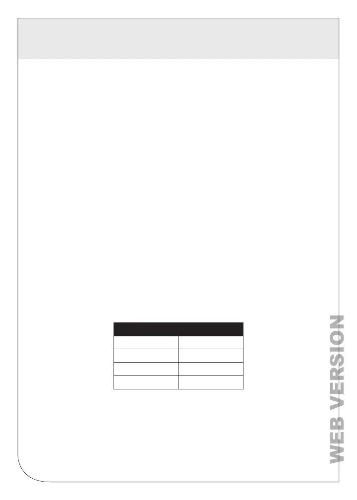
a. Each screw down terminal has at least a B and W position. Each conductor pair uses
a single terminal block. The table below provides the conductor termination guide;
conductor pairs are shown by row in the below table.
b. Some terminals have a R position; this position is for use with older 4-Port remotes and
their associated OCA, and would have a red conductor terminated to that terminal.
3.4.5 Remove fiber dust caps and clean connector end faces with a fiber
optic microfiber dry cleaner. Plug the LC or MTP
®
connectors into the
appropriate connectors on the rear of the Media Modules.
3.4.6 Connect the desired network equipment to the RJ45 ports on the front of
the Media Modules to communicate with the remote end devices.
3.4.7 Plug in and turn on all power supplies in the Power Injection Chassis.
B Terminal W Terminal
Black White
Blue
Yellow
Brown Orange
Purple Pink
 Loading...