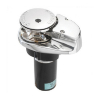
This document describes the Gen 2 S900/S2000 Stern Windlass, a marine anchor windlass manufactured by Lewmar. This product is designed for stern mounting on vessels and is intended for the deployment and recovery of anchors.
Function Description
The Lewmar Gen 2 S900/S2000 Stern Windlass is an electromechanical device for managing anchor rode (rope/chain) on a boat. It is specifically designed for stern installation, allowing for anchor deployment and retrieval from the aft of the vessel. The windlass features a gypsy that handles leaded lines with diameters between 12mm and 16mm (1/2" - 5/8"). It supports both powered operation and a manual controlled freefall mode for quick anchor deployment. A key feature is the auto-stop function, which automatically stops the windlass before the anchor reaches its final stowage position, enabling controlled anchor stowage. The system includes a motor/gearbox assembly, a drive cap, a control arm, and a rope guide. Electrical controls typically include a guarded rocker switch and a contactor assembly, with optional accessories like remote handheld controls and wireless remotes available.
Important Technical Specifications
The windlass comes in two main models, S900 and S2000, with distinct power and load capabilities:
S900 Model:
- Rope Diameter: 12-16 mm (1/2" - 5/8")
- Motor Supply Voltage: 12 V
- Motor Power: 600 Watt
- Working Load Limit: 200 kg (440 lb)
- Normal Current Draw: 85 Amp
- Circuit Breaker: 90 Amp (Part No 68000349)
- Weight: 11.6 kg (26 lb)
S2000 Model:
- Rope Diameter: 12-16 mm (1/2" - 5/8")
- Motor Supply Voltage: 12 V
- Motor Power: 1000 Watt
- Working Load Limit: 420 kg (924 lb)
- Normal Current Draw: 100 Amp
- Circuit Breaker: 110 Amp (Part No 68000350)
- Weight: 19.9 kg (44 lb)
General Electrical Specifications:
- Cable Sizing: Recommended cable sizes vary based on total length from the battery to the windlass, ranging from 16mm² (6 AWG) for 0-7m to 35mm² (2 AWG) for 15-22m, and up to 2 AWG for 50-73ft. Voltage drop over the complete wiring run must not exceed 10%.
- Control Switch: Guarded rocker switch (product ref 68000593) is supplied.
- Contactor Assy: S900 (68001213) and S2000 (68001214) specific contactor assemblies are provided.
- Optional Wireless Remotes: Available in 3-button (68000967) and 5-button (68000968) versions.
Dimensions (refer to diagrams for full details):
- S900: Overall length approximately 190mm, height approximately 262mm.
- S2000: Overall length approximately 190mm, height approximately 337mm.
- Bulkhead Thickness: Minimum recommended 25mm (1").
- Vertical Fall: Minimum 300mm (12") for the lead line when hauling in to prevent jamming.
Usage Features
- Anchor Rode Loading: The anchor rode is passed through the bulkhead roller unit, around the gypsy, and down into the locker. The control arm is pulled back to facilitate this, then gently released to keep the rode engaged. The end of the rode must be secured to a strong point.
- Powered Operation (Up/Down): The windlass is operated using a control switch (rocker switch, footswitch, or remote). For anchor release, the DOWN button is pressed for at least 2 seconds to initiate freefall. For retrieval, the UP button is pressed continuously.
- Manual Controlled Freefall: This method is used for quicker anchor deployment, in emergencies, or to conserve battery power.
- Disengagement: The windlass drive is disengaged by pressing the plunger button on the drive cap until it remains in the down position.
- Control: A Lewmar wrench is inserted into the capstan drive cap. Rotating clockwise grips the gypsy, while anticlockwise frees it, controlling the rate of descent.
- Re-engagement: To return to powered operation, the locking button is pulled out, disengaging the plunger. The circuit breaker/isolator is then engaged, and the UP/DOWN button is pressed.
- Safety Note: Always remove the wrench handle after use.
- Auto-Stop Sensor: This feature ensures controlled anchor stowage.
- Installation: The sensor is fitted to a bracket, and its cable is fed through a grommet. It must be secured away from moving parts and falling rode.
- Adjustment: With the anchor just below water level, the sensor height is adjusted to be within 6mm of the anchor rode. A wire coil (provided) is then fitted to the rode above the sensor at the marked position.
- Operation: When the anchor is lowered and then hauled in, the auto-stop activates, stopping the anchor as it breaks the water, allowing for final manual stowage.
- Maintenance: The brass wire coil should be checked regularly for wear and replaced if necessary. The motor direction must be checked upon installation to ensure the 'up' direction is correct and stops when the sensor connection is made.
Maintenance Features
- Regular Examination: Due to its exposed position, the windlass is subject to severe atmospheric attack and corrosion. Regular examination and operation are essential.
- Bedding-in Period (New Installation):
- Examine all electrical connections for soundness and corrosion. Tighten if necessary and protect.
- Check mounting screws for firm clamping and tighten if required.
- After Each Use:
- Wash down the windlass with fresh water.
- Ensure the rode is at least 300mm (12") below the windlass.
- Check the anchor locker drain.
- Check the rode for wear.
- Annually (or more often for frequent users):
- Repeat all checks from the bedding-in period.
- Check the gypsy as it is a high wear item.
- Gypsy Replacement/Service:
- Disassembly: Remove the screw and washer from the drive cap (may require warming if sealed with Loctite®). Depress the plunger and unscrew the free-fall mechanism (LH thread for stbd windlass). Remove stripper retaining screws, pull the control arm away, and remove the gypsy, noting the direction of rope teeth.
- Inspection & Cleaning: Check parts for wear and replace as appropriate. Clean thoroughly without solvent or wire brush and dry. Clean and lubricate the free-fall plunger.
- Reassembly: Use a small amount of grease on mating faces. Apply Loctite® to assembly screws, ensuring no residue on the driveshaft thread (which would prevent free-fall function). Tighten stripper retaining screws, then back off 1/2 turn to allow the stripper to lay loose on the gypsy.
- Troubleshooting: The manual provides guidance for common issues such as anchor rode paying out independently (tighten gypsy drive cap and secure rode independently), failure to operate or sluggish operation (check electrical connections, voltage, cable size, switches, circuit breaker, fuses, and motor), and complete failure to operate (check voltage at contactor/switches, solenoid, and motor).
- Safety: Always isolate the windlass using the circuit breaker/isolator before any maintenance or when not in use. Ensure the anchor rode is adequately secured to an independent strong point.