This document provides detailed instructions for remanufacturing Lexmark T650 Series toner cartridges. It covers the entire process from initial disassembly to final reassembly and includes troubleshooting tips and information on test prints. The Lexmark T650 series printers, introduced in March 2009, are high-performance machines with print speeds ranging from 45-55 pages per minute, based on a 1200 dpi engine. These printers are an evolution of the older Optra S machines but offer significantly faster performance. Due to their speed and fuser characteristics, the toner used in these cartridges is unique to this series.
Function Description
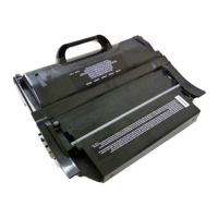
The Lexmark T650 Series toner cartridges are designed to deliver high-quality prints for the Lexmark T650 series of printers. These cartridges are available in various yield capacities, including 7K (7,000 pages), 25K (25,000 pages), and 36K (36,000 pages), and come in both "Return Program" (Prebate) and standard versions. The "Return Program" cartridges are sold at a special price with the agreement that the empty cartridge will be returned to Lexmark, and they typically include killer-type chips that prevent reuse until the chipboard is replaced. Standard cartridges, however, do not require chip replacement for reuse. The document highlights the significant profit potential in remanufacturing these cartridges due to their widespread use and the specific toner requirements.
The cartridges are designed with several components that work together to produce images. These include an OPC (Organic PhotoConductor) drum, a developer roller, a wiper blade, and various gears and seals. The OPC drum is crucial for image formation, while the developer roller transfers toner to the drum. The wiper blade cleans the OPC drum, and the retaining blades prevent toner leakage. A shipping lock is an essential feature, designed to protect the OPC drum and developer roller during transit and storage by preventing contact between the toner hopper and the drum, thereby avoiding flat spots.
Usage Features
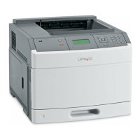
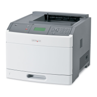
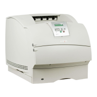
The document details the physical differences between the T65x series cartridges and older Optra and T series cartridges, illustrating various cartridge versions (Optra S, Optra SE, Optra T, T-520, T-620, T-630, T-640, T-650) to help users identify and understand the specific design of the T650 series. This visual guide is important for proper handling and remanufacturing.
The cartridges are region-specific, with different part numbers for Americas, Europe/Middle East/Africa (EMEA), Latin America, and Asia Pacific. While the physical cartridges are largely similar across regions, the chips embedded within them dictate compatibility. The document also mentions specific label cartridges (T654X04A and T650H04A) and notes that extra high yield (36K) cartridges are only listed for the T654 series. Attempting to install these EHY cartridges in T650/652 machines will result in an "Unsupported Cartridge" error, indicating a built-in usage restriction.
The instructions emphasize the importance of the encoder wheel, which determines whether a cartridge is a Prebate or Non-Prebate type. The chip, on the other hand, communicates the cartridge's yield to the machine. Damage to either of these components can affect the cartridge's functionality and acceptance by the printer.
Maintenance Features
The remanufacturing process is a comprehensive maintenance procedure designed to restore an empty toner cartridge to full functionality. It involves several steps, each requiring specific tools and materials.
- Toner approved vacuum
- Small screwdriver (common style)
- Phillips head screwdriver (#1)
- Needle nose pliers
- Spring hook
Required Materials:
- T650 toner
- Drum padding powder
- Cotton swabs
- Isopropyl alcohol
- Cotton pads
- Long life OPC drum (optional)
- Wiper blade
- Shipping lock
- Recovery blade (optional)
- Retaining blades (optional)
Disassembly Steps:
- Vacuuming: The exterior of the cartridge is vacuumed, taking care around the drum.
- Spring Removal: Two springs from each end of the cartridge are removed using a spring hook.
- Hopper Separation: The toner hopper is separated from the cartridge shell by releasing plastic posts and lifting the hopper.
- Drum Axle Plate Removal: Two small screws are removed from the drum axle plate, and the plate is pressed out from the inside. The small helical gear is held to prevent drum damage.
- Locking Ring and Drive Gear Removal: On the opposite side, a locking ring is turned until it spins freely, then carefully pried off along with the white drive gear.
- Drum Removal: The OPC drum is gently lifted out and placed in a light-protected area if it is to be reused.
- Wiper Blade Removal: The contact spring and two screws on either end of the wiper blade are removed.
- Foam Seal Cutting: A razor blade is used to cut the foam seal along the back edge of the wiper blade, separating it from the cartridge. Care is taken to cut along the plastic/foam, not the blade.
- Wiper Blade Detachment: The cartridge is held upright, the laser shutter is held open, and the wiper blade is carefully removed to avoid breaking the alignment pin.
- End Foam Inspection: The two end foams are inspected and cleaned.
- Encoder Wheel Removal: The encoder wheel is gently pried off the center shaft of the supply hopper using needle nose pliers, taking care not to damage it or pull the shaft through the clutch gear.
- Fill Plug Removal and Toner Dump: The fill plug is removed, and all remaining toner is dumped out.
- Developer Roller Drive Gear Removal: The developer roller drive gear is turned to unlock it and then removed from the shaft.
- Doctor Blade Spring Removal: The doctor blade spring is removed by pressing down on its center.
- Developer Roller Cover Removal: The developer roller cover is removed by releasing a tab and sliding it out.
- Developer Roller Bushing Removal: A small metal bushing on the left side of the static roller is pried up to release the developer roller.
- Developer Roller Removal: The developer roller is removed. It's crucial to remove the doctor blade spring before removing the developer roller to prevent damage to the doctor blade alignment. The toner hopper is then vacuumed or blown clean.
- Seal Cleaning: Developer roller seals and the electrical contact are cleaned with a cotton swab dipped in alcohol. The developer roller is carefully vacuumed or blown off without touching it.
- Doctor Blade Removal: The doctor blade is slid down out of its track.
Reassembly Steps:
- Retaining Blade Inspection: Inner and outer retaining blades are inspected and replaced if bent.
- Doctor Blade Installation: The doctor blade is cleaned and installed, ensuring the contact spring is on top.
- Developer Roller Installation: The longer keyed end of the developer roller is placed into the cartridge, and the roller is installed.
- Bushing Installation: The bushing is installed onto the developer roller shaft, with the tab facing down to lock the roller.
- Doctor Blade Spring Installation: The doctor blade spring is installed.
- Toner Filling: The hopper is filled with the appropriate amount of toner, mindful that the chip controls the maximum amount. The fill plug is then installed.
- Developer Roller Cover Installation: The developer roller cover is installed, ensuring pins are correctly aligned.
- OPC Drum Lubrication and Installation: The OPC drum is lightly coated with lubricant and placed into the cartridge, ensuring the long thin axle is on the contact/non-chip side and the spring is in the proper position.
- Drum Axle Plate Installation: The drum axle plate and its two screws are installed.
- Black Plastic Bushing Installation: On the opposite side, the black plastic bushing is installed and turned until it locks. The white gear inside the bushing is pressed.
- Toner Hopper Installation: The toner hopper is installed left side first, ensuring the left side post and white bearing are in their proper slot.
- Right Side Post Alignment: The cartridge shell is pulled out on the right side so the right side post falls into its slot.
- Spring Replacement: Both springs are replaced onto the toner supply chamber using a spring hook.
- Developer Roller Drive Gear Re-installation: The developer roller drive gear is re-installed, holding the gear train and turning the gear until it locks.
- Chip Replacement: The old chip is removed by unscrewing and sliding it out, and a new chip is installed with the contact side facing the cartridge.
- Shipping Lock Installation: A shipping lock is installed by pressing two red tabs into the sides of the cartridge. This prevents contact between the toner hopper and the OPC drum, protecting both components during shipping and storage.
Troubleshooting and Test Prints:
The document includes a "Cartridge Repetitive Defect Chart" with measurements for the OPC drum (94mm), developer roller (62mm), and PCR (38mm) to help diagnose print quality issues. It also lists "Machine Error Codes," specifically "42.xy" for cartridge region mismatch, where 'x' is the printer region and 'y' is the cartridge region. Region codes are provided (0: Worldwide, 1: America, 2: Europe, 3: Asia, 4: Latin America, 9: Invalid region).
Instructions for "Taking Test Prints" are provided:
- Press the MENU key.
- Navigate to "CONFIG MENU" using the DOWN ARROW.
- Press the SELECT button.
- Navigate to "PRT QUALITY PAGES" using the DOWN ARROW.
- Press the SELECT button.
These pages include device information, printer revision, cartridge information, printer margin settings, and minimum stroke width, which are vital for verifying the cartridge's performance after remanufacturing.