POWER TILT AND POWER TELESCOPIC STEERING COLUMN SYSTEM > IG Power Source Circuit
for Preparation Click here
DESCRIPTION
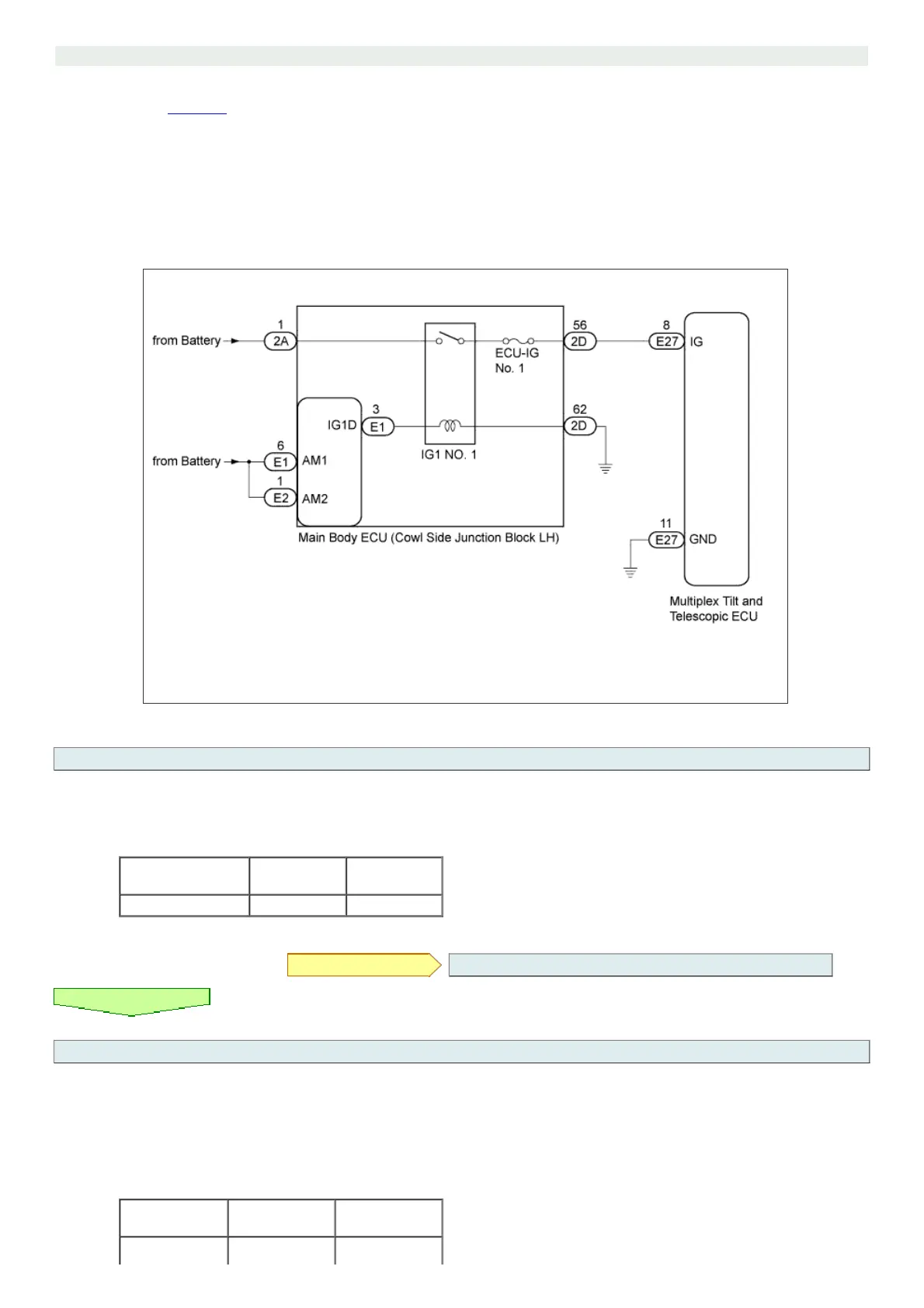
When the engine switch is turned on (IG), the IG power source circuit supplies positive (+) voltage to the multiplex tilt and telescopic ECU.
The multiplex tilt and telescopic ECU also receives engine switch signals via this circuit.
WIRING DIAGRAM
INSPECTION PROCEDURE
1.INSPECT FUSE (ECU-IG No. 1)
a. Remove the ECU-IG No. 1 fuse from the main body ECU.
b. Measure the resistance of the fuse.
Standard Resistance:
Tester Connection Condition
Specified
Condition
ECU-IG No. 1 fuse Always Below 1 Ω
NG REPLACE FUSE
OK
2.CHECK MULTIPLEX TILT AND TELESCOPIC ECU (IG TERMINAL VOLTAGE)
a. Disconnect the E27 connector from the multiplex tilt and telescopic ECU.
b. Measure the voltage according to the value(s) in the table below.
Standard Voltage:
Tester Connection Switch Condition
Specified
Condition
E27-8 (IG) - E27- Engine switch on