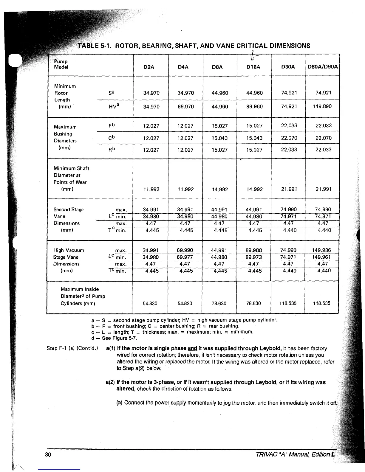
E 5-1. ROTOR, BEARING, SHAFT, AND VANE CRITICAL DIMENSIONS
D2A
D4A
D8A
D16A
D30A
D60A/D90A
Minimum
Rotor
Sa
34.970
34.970
44.960
44.960
74.921
74.921
Length
(mm)
HV
a
34.970
69.970
44.960
89.960
74.921 149.890
Maximum
Fb
12.027
12.027
15.027
15.027
22.033
22.033
Bushing
Cb
12.027 12.027
15.043 15.043
22.070 22.070
Diameters
(mm)
Rb
12.027 12.027
15.027 15.027
22.033 22.033
Minimum Shaft
Diameter at
Points
of
Wear
(mm)
11.992 11.992
14.992
14.992 21.991
21.991
Second
Stage
max.
34.991 34.991
44.991
44.991
74.990
74.990
Vane
L
C
Dimensions
(mm)
TCmin.
High
Vacuum
Stage
Vane
Dimensions
(mm)
TC
Maximum Inside
Diameter
d
of
Pump
Cylinders
(mm)
54.830
54.830
78.630
78.630 118.535 118.535
a -
S = second stage pump cylinder;
HV
= high vacuum stage pump cylinder.
b - F = front bushing; C = center bushing; R = rear bushing.
c - L
:;
length; T = thickness; max. = maximum; min. = mrnimum.
d -
See
Figure 5·7.
Step
F·l
(a)
(Cont'd.)
a(1)
If
the
motor
is
single
phase
!ill!
it
was
supplied
through
Leybold,
it has been factory
wired for correct rotation; therefore, it isn't necessary
to
check motor rotation unless you
altered the wiring or replaced the motor.
If
the wiring was altered or the motor replaced, refer
to
Step a(2) below.
a(2)
If
the
motor
Is
3-phase,
or
if
it
wasn't
supplied
through
Leybold,
or
if
its
wiring
was
altered, check the direction of rotation as follows:
A
'k!:
(a)
Connect the power supply momentarily to jog the motor, and then immediately switch it
oft
"I
1:1,
"
30
TRIVAC
"A
II
Manual,
Edition L