F-6
CAUTION:
FAILURE
TO ENSURE
THAT
THE O-RINGS (47)
REMAIN
IN
THEIR
GROOVES
DURING
MODULE ASSEMBLY
WILL
RESULT IN DAMAGE TO THE O-RINGS
AND
POOR
PUMP PERFORMANCE.
NOTE: The module assembly
sequence
(Steps
F-6a
through F-6j)
is
designed
to
keep the loose O-ring facing uP.
so
that
it
does
not
fall
out
of
its O-ring groove.
CAUTION:
WHEN ASSEMBLING THE MODULE.
DO
NOT
SCRATCH THE ENDS OF THE ROTORS
OR
THE INSIDE SURFACES OF THE PUMP CYLINDERS
OR
END PLATES. SCRATCHES TO THESE SUR-
FACES COULD RESULT IN
POOR
PUMP PERFORMANCE.
NOTE: To ensure
that
each
part
is
oriented correctly. refer
to
Figure 5-3 and
follow
each
step precisely (Steps
F-6a
through F-6j).
REQUIRED
ACTION:
Assemble the module
as
follows:
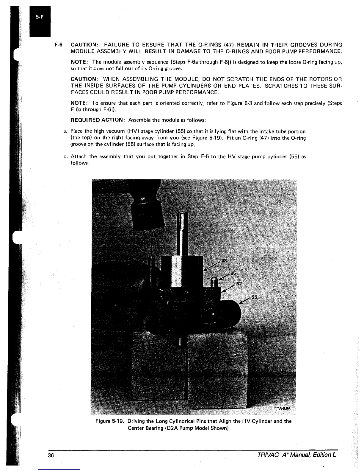
a.
Place
the high vacuum
(HV)
stage
cylinder (55)
so
that
it
is
lying
flat
with
the intake tube portion
(the top) on the right facing away from you
(see
Figure 5-19).
Fit
an
O-ring (47)
into
the O-ring
groove
on
the cylinder (55) surface that
is
facing
uP.
b.
Attach the assembly
that
you
put
together in Step F-5
to
the
HV
stage
pump cylinder (55)
as
follows:
Figure 5-19. Driving the Long Cylindrical
Pins
that
Align the
HV
Cylinder
and
the
Center Bearing
(D2A
Pump Model Shown)
TRIVAC
"A"
Manual,
Edition L