Do you have a question about the LF Bros E Series and is the answer not in the manual?
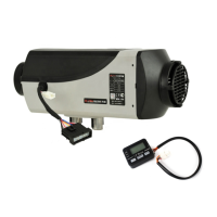
Describes the main structure of the heater as depicted in Fig. 2.
Explains the case structure, fan motor, air inlet, and hot air outlet.
Details the controller's mounting, function, and monitoring of heater procedures.
Explains adjustment and control during the heater's operating cycle.
Lists conditions for automatic shutdown and protection, and how to cancel it.
Identifies circuit interfaces on the controller outer case, referencing Fig. 4.
Details the functions of flame, overheating, and temperature sensors for safety.
Explains the dual function of the glow plug as a flame sensor for ignition and continuous burning.
Describes the overheating sensor's role in preventing damage by cutting fuel supply.
Explains how the temperature sensor measures air inlet temperature to adjust output.
Explains the heater's power supply from the car and fuse protection.
Details the fuel source and delivery mechanism for the heater.
Lists mandatory requirements and places of application for heater installation.
Covers location and spacing requirements for installing the main heater unit.
Discusses installing the heater inside or outside the vehicle and protection from elements.
Details necessary clearance for air flow, installation, and maintenance, referencing Fig. 6.
Emphasizes proper sealing between the heater and installation surface using a gasket.
Addresses the need for a mounting plate for thin panels and sealing between plate and body.
Specifies the correct installation direction and tilt angle for the heater to ensure normal operation.
Advises checking the fan wheel for contact or friction with surrounding components post-installation.
Covers air circulation modes, temperature resistance, and pressure drop for the heating system.
Recommends independent outer or inner circulation modes for the heating system.
Specifies material requirements for external heating air pipes to withstand 150 °C.
Sets the maximum allowable pressure drop for the air heating system at 0.3 kPa.
Warns about hot air eruption and potential vent blockage by passengers.
Advises drawing inlet air from cold areas to avoid re-entering hot air in internal circulation.
Guides the installation of the fuel tank, filter, connecting pipe, and fuel pump.
Details securing the fuel pump with rubber clamps and the required upward tilt angle.
Explains how elevation differences affect fuel pressure and provides dimensional requirements.
Instructs on installing the fuel filter correctly at 90° before the fuel pump inlet.
Covers wiring harness, battery, fuel pump, and control panel connections.
Details routing, fixing, and protecting the main wire harness with corrugated pipe.
Instructs on connecting the red wire to the battery's positive terminal and black to negative.
Simple instruction to connect the fuel pump leads.
Guides placement and connection of the control panel for easy operation.
Advises wrapping wire ends with insulating tape to prevent short circuits.
Focuses on installing air inlet and exhaust pipes, ensuring separate circuits.
Explains the need for fresh air intake and exhaust discharge, preventing fumes re-entry.
Details using provided aluminum/stainless steel pipes and clamps, keeping protective hoods intact.
Guides pipe direction, condensate discharge, bending radius, and angle limits, referencing Fig. 16.
Advises arranging pipes to prevent openings from blocking by dirt, snow, or slurry, referencing Fig. 17.
Warns about exhaust pipe heat and installation distance from flammable parts, referencing Fig. 18.
Recommends a protective cover for exhaust pipe sections inside the vehicle to prevent burns.
Details removing air from the fuel line using the fuel pumping mode after installation.
Advises commissioning the heater, checking for leaks, smoke, or noise, and turning off if issues arise.
Outlines seasonal inspection points including contamination, connections, and pipe integrity.
Recommends running the heater every four weeks if not in use to prevent mechanical part malfunction.
Stresses keeping air inlet and outlet ports clean and unblocked for smooth airflow and to prevent overheating.
Instructs on operating the heater for 15 minutes after refueling to fill the lines, and turning off before refueling.
Specifies a 5-year replacement period for the heat exchanger and exhaust pipe, and sensor replacement.
Advises detaching the positive power wire from the battery when welding the vehicle to protect the controller.
Sets ambient temperature limits for transportation and storage to prevent electronic component damage.
States that only authorized stations can install/repair, and prohibits non-original parts.
Clarifies manufacturer's non-responsibility for damage due to unauthorized opening or non-compliant installation/operation.
Illustrates and describes various operational modes like startup, shutdown, and fixed settings.
Explains the fuel pumping mode for removing air locks or filling lines after refueling.
Details the sequence of events during a normal heater startup, including glow plug and fuel pump operation.
Describes running the heater at a constant, selectable power output regardless of temperature.
Explains how the heater adjusts power to maintain a set ambient temperature.
Details the shutdown process where the pump stops, but the fan continues cooling.
Addresses residual fuel after power interruption during operation.
Describes the process of blowing out residual fuel after an unclean shutdown.
Introduces control methods using mechanical, LCD with buttons, and LCD with knob panels.
Explains the components and operation of the mechanical control panel, including modes.
Details setting a fixed power output using the mechanical control panel's knob and button.
Explains setting a desired temperature using the mechanical control panel's knob and button.
Describes shutting down the heater using the mechanical control panel's knob.
Provides steps to start the heater after an unclean shutdown using the mechanical control panel.
Introduces the LCD control panel featuring buttons for operation and display.
Guides initiating fuel pumping mode using the LCD control panel with buttons.
Details the startup sequence for the LCD control panel with buttons, including voltage display.
Explains setting a fixed power output using the LCD control panel with buttons.
Guides setting a desired temperature with the LCD control panel with buttons.
Describes the shutdown procedure using the LCD control panel with buttons.
Details starting the heater in ventilation mode after an unclean shutdown using the LCD panel.
Introduces the LCD control panel featuring a knob for operation and display.
Guides initiating fuel pumping mode using the LCD control panel with knob.
Details the startup sequence for the LCD control panel with knob, including voltage display.
Explains setting a fixed power output using the LCD control panel with knob.
Guides setting a desired temperature with the LCD control panel with knob.
Describes the shutdown procedure using the LCD control panel with knob.
Provides general advice for restarting the heater and preventing circuit malfunctions.
Lists display indicators for common issues like disconnected wiring or power failures.
Explains display messages indicating disconnected wiring harnesses and their specific wire colors.
Describes how power failures are treated during startup vs. operation, and restart procedures.
Explains display messages like LOST/LOS indicating an unclean shutdown and waiting for processing.
Mentions that the device detects faults and displays error codes like E07, referencing Figs. 43/44.
Lists error codes, fault descriptions, and possible causes/solutions for troubleshooting.
Provides a table for logging maintenance dates and causes.
Includes warranty, qualification, usage inquiry, and station contact information.