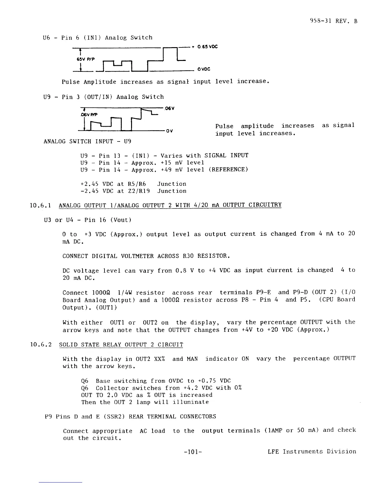
U6
-
Pin
6
(iN1)
Analog Switch
958-31
REV.
B
as
signal
Pulse Amplitude increases
as signal
U9
-
Pin 3
(OUT/IN)
Analoe Switch
ANALOG SWITCH INPUT
-
U9
U9
-
Pin 13
-
(INl)
-
Varies
with
U9
-
Pin 14
-
Approx.
+15
mV level
U9
-
Pin 14
-
Approx.
+49
rnV level
+2.45
VDC at R5/R6 Junction
-2,45
VDC
at Z2lRl9 Junction
o.65
voc
ovoc
input
level
increase.
Pulse
arnplitude
increases
input
1eve1
increases.
SIGNAL
INPUT
(REFERENCE)
ov
l0
.6.
l
U3
ANALOG OUTPUT 1 /ANALOG OUTPUT
2
WITH
4 20 mA
OUTPUT
CIRCUITRY
or U4
-
Pin 16
(Vout)
0 to
+3
VDC
(Approx.
)
output
level
as output
current
is changed
from
4 mA
to 20
mA
DC.
CONNECT
DIGITAL
VOLTMETER
ACROSS
R3O
RESISTOR.
DC voltage level can vary from
0.8
V
to
+4
VDC as lnput
c-urrent is chanted
4 to
20 mA DC.
Connect 10000 1/4W resistor
across
rear terminals
P9-E and
P9-D
(OUT
2)
(IiO
Board Analog Output) and a 10000
resistor
across P8
-
Pin
4 and P5.
(CPU
Board
0utput).
(OUTl)
I.Jith
either OUTl or OUT2 on
the display,
vary the
percentage
0UTPUT
wj.th the
arrow keys and note that the OUTPUT
changes
from
+4V
to
+20
VDC
(Approx.
)
i0.6.2
SOLID STATE RELAY OUTPUT 2 CIRCUIT
With
the display in
OUT2 XX% and MAN
with the arrow kevs.
indicator
0N vary the
percentage
OUTPIIT
Q6
Base switching
from OVDC to
+0.75
VDC
Q6
Collector
switches from
+4.2
VDC with
0%
OUT TO 2.0 VDC as % OUT is
increased
Then the
OUT 2 lamp
will illuminate
P9 Pins D and
E
(SSR2)
REAR
TERMINAL CONNECT0RS
Connect
appropriate AC load
to the output
terminals
out the
clrcuit.
(
1AMP or
50
mA)
and check
LFE
Instruments
Division
-10i-


 To Next Page
 Loading...