958-3I
REV.
B
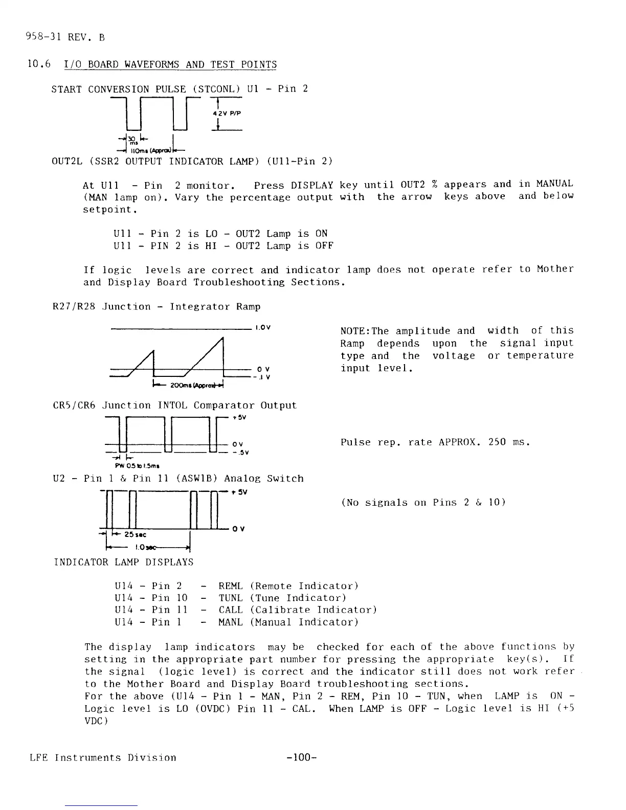
10.6
I/O BOARD WAVEFORMS
AND
TEST POINTS
Flv
05 b
l.5mr
I
&
Pin 1l
(ASWIB)
Analog
Swrt
ch
-r5V
Pulse rep. rate APPROX. 250
ms.
(No
sitnals
on
Pins
2 & 10)
ov
-.tv
INDICATOR LA}IP DISPLAYS
REML
(Rernote
Indlcator)
TUNL
(Tune
Indicator)
CALL
(Calibrate
Indicator)
I'{ANL
(Manual
Indicator)
START CONVERSION PULSE
(STCONL)
UI
_
PiN
2
-l
rl--
| | | |
4.2vP/P
UUi
-'i*,L
I
--{
ttOnr
(lordl.-
OUT2L
(SSR2
OUTPUT
INDICATOR
LAMP)
(Uli_Pin
2)
r5V
ov
-.5v
At Uli
-
Pin 2 monitor.
Press
DISPLAY
key until
OUT2 % appears
and
ln
MANUAL
(|,lAN
lamp on).
Vary
the
percentate
output
with the
arrow keys
above
and
below
setpoint.
Ul l
-
Pin 2 i.s L0
-
0UT2 Lamp
is 0N
Ul I
-
PIN 2 is HI
-
0UT2 Lamp is
OFF
If
logic levels are correct and indicator
lamp does
not operate
refer
to Mother
and Display Board Troubleshooting Sections.
R27
lR28
Junction
-
fntegrator Ram
p
t.o
v
NOTE:The amplitude
and
\^ridth
of
this
Ramp
depends upon the
signal
lnput
type and the
voltate or
temperature
input
1eve1.
CR5/CR5 Junction INTOL Comparator Output
-L-
L
l--
zoo-.
hmrol-l
25
rrc
I
-roH
Ul4
-
Pl-n 2
U14
-
Pin
10
Ul4
-
Pln l1
-
U14
-
Pin I
The
drsplay
lamp indicators may
be checked
for each
of the above
functions
by
setting in the appropriate
part
number
for
pressing
the appropriate
key(s).
If
the signal
(loeic
level) is correct
and
the indicator still
does not
work refer
to the Mother Board
and
Display Board
troubleshooting sections.
For the above
(Ul4
-
Pin I
-
MAN, Pin
2
-
REM, Pin
l0
-
TUN, when
LA.|{P
is
ON
-
Logic level is L0
(OVDC)
Pin 1l
-
CAL.
When
LAI'IP is OFP
-
Logic
leve1
j,s
tll
(+5
VDC
)
LFE Instruments Divrslon
-
100-


 To Next Page
 Loading...