EasyManua.ls Logo

LFE 2000 Series - Page 106

LFE 2000 Series
155 pages
Print Icon
To Next Page IconTo Next Page
To Previous Page IconTo Previous Page
Loading...
ALARM
2 INDICATOR
(ALM2L)
P2
-
Pin
43
Connector
If ALM2 lamp does not
illuminate
when ALARM
arrow keys, check the following:
ul
-
Pin 10
-
LAI'IP
is OUT
when HI
(+4.2
VDC)(Q7
Ul
-
Pin 10
-
LAMP is ON
when LO
(O
VDC)(Q7
Coi
If larnp circuit is
operational,
but relay
is
circuit as well as relay
circuit
(K1
)
DISPLAY RESET Ul
-
Pin 14
(DRSTL)
958-3i
REV
2
display
is exercised
Collector
is
LO)
lector
is
HI
)
not
switching
check
Q7
with
the
and
U8
power
is first
applied,
then
pulse
up
to HI
power
is removed.
DRSTL
is
inirially
Lo
(ovDC)
when AC
(+5
VDC)
and remains
there
untll AC
Ul
-
Pin
10
(DISPLAY
DATA)
Ul
-
Pin
1l
(DSCKH)
Display
Serial
Clock
to Display
Board
Same
essential waveform
as
Ul
-
Pin
10 above.
OUTIL
(SSRI
OUTPUT
INDICATOR
T,Aj'{P)
Display
OUT I XX% and in
I'{ANUAL
(MAN
lamp
on)
vary
the
arrow keys above
and below
setpoint.
the
percentage
output
with
U10 Pln 2 is
L0
-
LAMP
IS 0N
(OVDC)
UlO PiN 2 iS HI
-
LAMP
IS OFF
(+4.2
VDC)
UlO Pin 3 is Lo
-
LAMP IS
oN
(OVDC)
UIO PiN 3
iS HI
-
LAMP
IS OFF
(+4.2
VDC)
If logic levels
are correct
and indicator
lanp
does not operate,
refer
to
Dlsplay and
Mother Board
Sections.
P8 Plns
4
and
5 Connector
-
SSR1 OUTPIJT
Connect the AC load
appropriate
to the
triac
(terrnlnals
P8
-
4+5). Use
standard
troubleshooting
procedures
to check
out
the solid
state
relay
circuit.
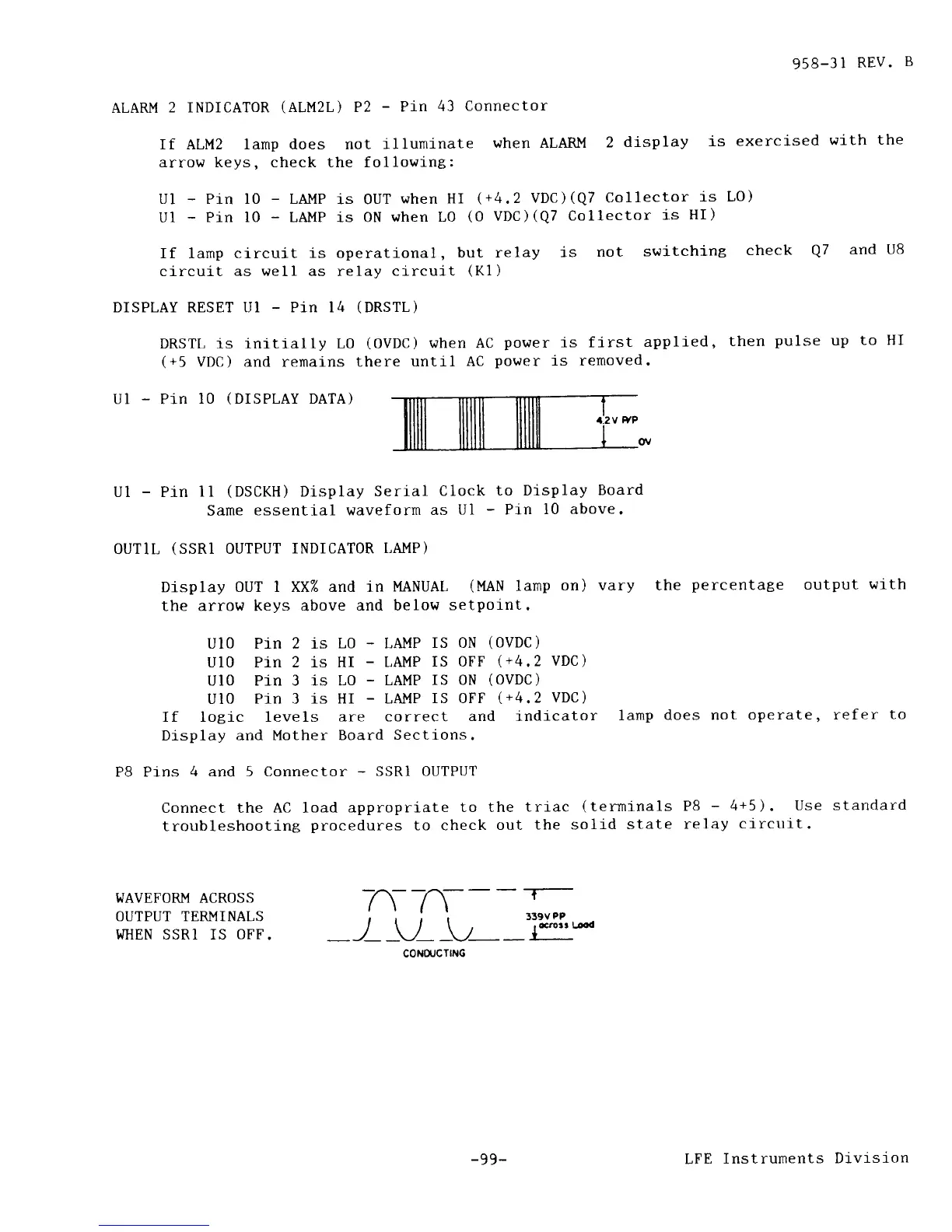
WAVEFORM ACROSS
OUTPUT TERMINALS
WHEN SSRI IS
OFF"
CONOIJCTING
-99-
LFE
Instrunents
Division