EasyManua.ls Logo

LFE 2000 Series - Page 105

LFE 2000 Series
155 pages
Print Icon
To Next Page IconTo Next Page
To Previous Page IconTo Previous Page
Loading...
958-31
REV.
B
10.5.5 DISPLAY
STABLE
BUT WRONG
Check
ribbon
cable between
the
I/0
and
the CPU
points
and note
that
the
waveform
indicated
correct.
CAUTION:
D0
NOT PROBE Ul
-
Pin
18. This
rs
a
added
capacitance
of
the
scope
prove
MAY
oscillator
and
cause display
"DATA
LOST/PLEASE
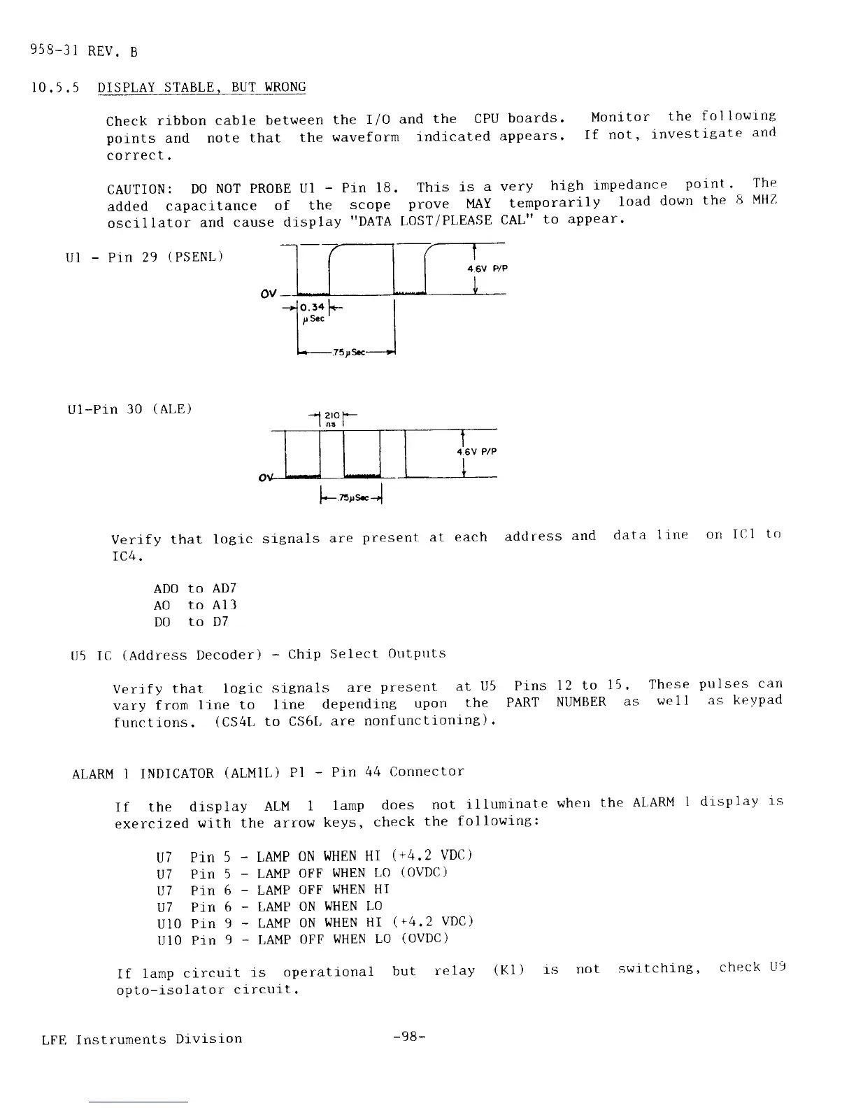
Ul
-
Pln
29
(PSENL)
75;Sc
U I
-Pr-n
3O
(ALE)
Verify
that
logic
signals
are
present
IC4.
ADO
to
AD7
AO
to All
D0
to D7
tl5
IC
(Address
Decoder)
-
Chip Select
Outptrts
Verr f
y
that.
logi-c
slgnals
are
present
at
U5
vary
from
line to line
depending
upon
the
functions.
(CS4t,
to CS6t,
are
nonfunctioninB).
ALARM
I INDICATOR
(ALMIL)
Pl
-
Prn
boards.
Monitor
the
fol
lowrnB
appears.
If
not,
investi-gate
and
very
high
inPedarrce
Point.
The
temporarilY
load
down
the
8
MHZ
CAL"
to appear.
at
each
address
and
data
line
orr
ICI
tct
Pins
12 to
15.
PART
NIIMBER
as
These
pulses
can
well
as keypad
If the
disPlaY
ALM
1
lamP
exerctzed
with
the arrow
keYs,
U7
PiN
5
_
LAMP
ON WHEN
U7
Pin
5
-
LAMP
OFF
I'JHEN
U7
Pin
6
-
LAMP
OEF
WHEN
U7
Pin
6
-
LAMP
ON
WHEN
U10
Pln
9
-
LAMP
0N
WHEN
Ill0
Pin
9
-
[,AMP
OFF
WHEN
If
lamp
circult
is
oPeratfona
opto-isolator
circuit.
LFE
Instruments
Divlsion
44
Connector
does
not i
l lurninat
e
whett
the
check
the fol
I owing:
HI
(+4.
2
VDtl
)
LO
(OVDC)
HI
LO
HI
(
+4.2
VDC
)
LO
(OVDC)
I
but
relay
(Kl
)
rs
AL,ARM
1 drsP
laY
rs
_,1
2ro
f._
I n3
|
l.-or*.J
-98-
not
switchin8,
check
LI9