EasyManua.ls Logo

LFE 2000 Series - Page 104

LFE 2000 Series
155 pages
Print Icon
To Next Page IconTo Next Page
To Previous Page IconTo Previous Page
Loading...
958-31
REV.
B
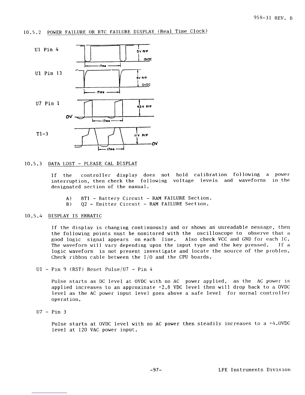
10.5.2
POWER
FAILURE
0R RTC
FAILURE
DISPLAY
(Real
Time
Clock)
Ul
Pin
4
Ul Pin
l3
U7 Pin
I
Tl-3
I0.5.3 DATA LOST
_
PI,EASE
CAL DISPLAY
If the
controller
display
does
not
hold
calibration
followlng
a
po\ter
interruption,
then check
the
following
voltage 1eve1s
and
waveforms 1n
the
designated
section
of the manual.
A) BTI
-
Battery Circuit
-
RAM
FAILURE Section
B)
Q2
-
Emitter
Circuit
-
RAI'I FAILURE
Section.
DISPLAY IS ERRATIC
If
the display
is
changing continuously
and
or shows an
unreadable message,
then
the following
points
must be
monitored
with the oscilloscope
to observe that a
good
logic
signal appears on each
line. Also
check
VCC and GND for
each IC.
The
waveform will vary
depending
upon the input
type
and the key
pressed.
If a
logic waveform is not
present
investitate
and
locate the
source
of the
problem.
Check ribbon cable between the
I/0 and
the CPU boards.
-
Pin 9
(RST)
Reset Pulse
lU7
-
Pin
4
10.5.4
UI
Pulse
starts as
DC level at OVDC
wrth no AC
appiied increases
to an approximate
+2.8
VDC
level
as
the AC
power
input level
goes
above
ope rat fon
.
power
applied,
as the AC
power
rs
level then
will drop back to a
0VDC
a safe
level for
normal controller
U7-Pin3
Pulse starts at OVDC level
wi-th no AC
power
then steadily
increases
to a
+4.0VDC
level at 120 VAC
power
input.
-97 -
LFE
Instruments
Dtvtsron