EasyManua.ls Logo

LFE 2000 Series - Page 103

LFE 2000 Series
155 pages
Print Icon
To Next Page IconTo Next Page
To Previous Page IconTo Previous Page
Loading...
958-ll
REV.
B
RAM FAILURE
RAM
Thrs
display
should
appear
on
po\der
up
if
the
unit
is
urrable
to
wrrte
to
FAILURE
andi
or read
f rom
the
cPU RAI'{
(memory)
chip
(u3).
This
is
probably
catrsed
byadefectiveRAMcircurt.ChecksignalsontheCPUboard.
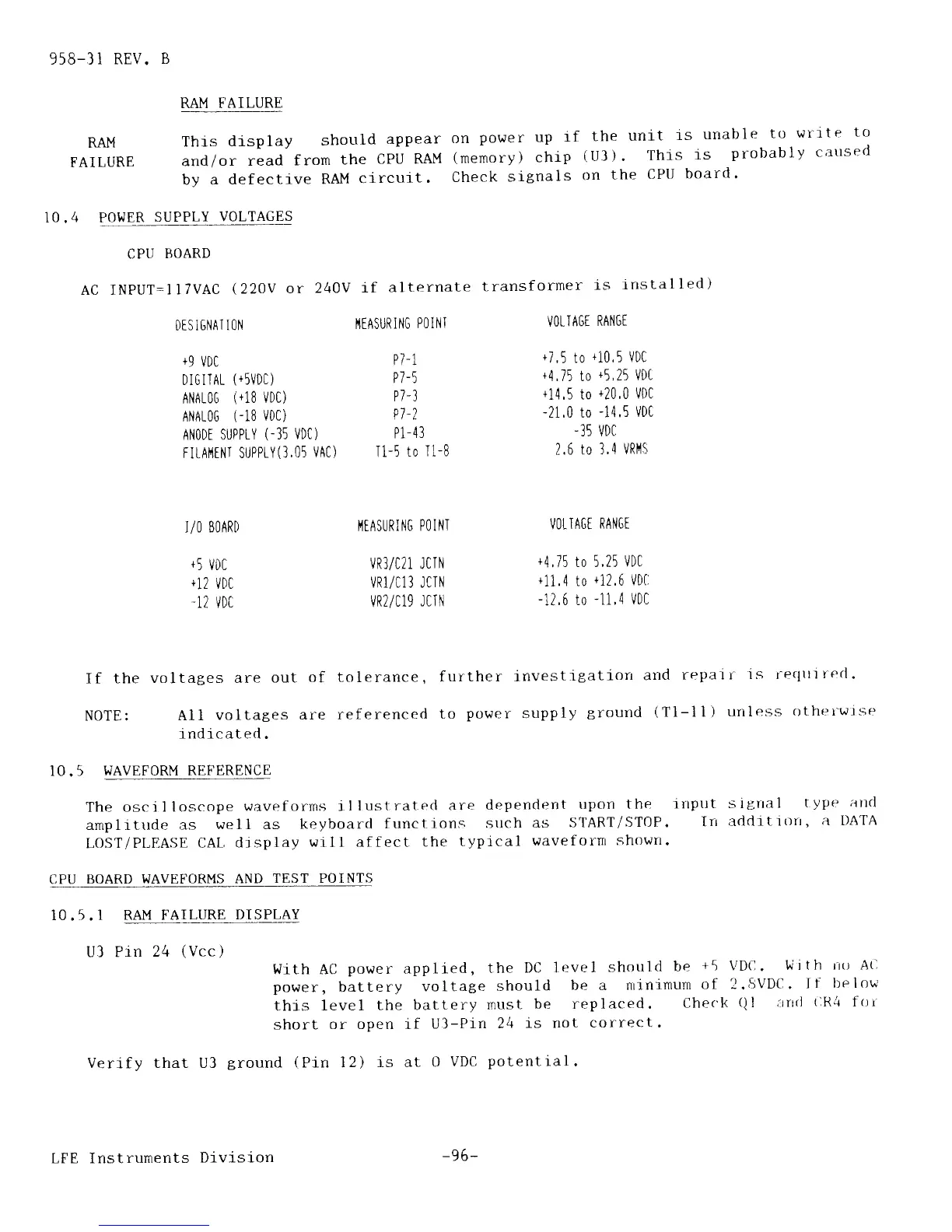
10.4 POWER
SUPPLY
VOLTAGES
CPU
BOARD
AC INPUT:IlTVAC
(22OV
or
24OY
if
alternate
transformer
is
lnstalled)
DISIGNATI0|II'{EASURI|.IGP0INTV0LTA6[RAltlG[
+9
VDC
Pl-l
+7'5
to
+10'5
VDC
DIGITAL
(+5VDC)
P7-5
+4,75
to
+5,25
VDt
ANAL0G
(
+18
VDC)
P7-3
+14,5
to
+20,0
VDC
ANAI0G
(-18
VDC)
P7-?
-21'0
to
-14'5
VDI
ANODT SUPPLY
(-35
VDC)
P1-43
-35
VDC
FILAi{ENI SUPPTY(].05
VAC)
T1-5
tO
T1-B
2.6
tO J,4
VRI'IS
I/O
BOARD
+5
VDC
+12
VDC
-12
VDC
l'{[ASUR
ING P0 INI
vR3/C21 JCIN
VR1/C13
JCIN
VR2/C19
JCIN
VOLTAGi
RAIiGT
+4,75
to 5,25
VDC
+11
,4 to
+i2,6
VD(,
-12,6
to
-11,4
VDl]
If
the
voltages are
out
of t-olerance,
further
lnvestiSatiorr
and
repalr
is recltlirecl .
NgTE:
All
voltages
are ref
erenced
to
power
supply
Bround
(Tl-11)
uriless
rltht-'rwlse
indicated.
IO.5
WAVEFORM REFERENCE
The
osci I loscope
wavefclrms r
llustratecl
are
dependent
upcln
the
irtput
sigrral
typer
alld
amplrtrrde
as
well as
keyboarcl
f unctions
sttch
as
START/ST0P.
Irr
addrtitln,
a DATA
LOST/PLEASE
CAL
djsplay
w11l
affect
the
typical
waveforn
shown.
CPU
BOARD WAVEFORMS
AND
TEST POINTS
10.5. I
RAM FAILURE
DISPLAY
U3 Pin
24
(Vcc)
Wlth AC
po\rer
applied,
the
DC lr:vel
shottlcl
be
+5
VDC.
With
rro A(l
power,
battery
voltage
should
be a
nrinirnurn
of 2.svDil .
I
f
lle I ow
this leve1
the
battery
must-
be replaced.
Checl<
()l
art(l
(lR4
f
(rr
short
or open rf
U3-Prn
24
is not
correct.
Verify that U3
ground
(Pin
12)
is at
0
VDC
potentlal.
LFE Instrunents
Division
-96-