EasyManua.ls Logo

LFE 2000 Series - Page 51

LFE 2000 Series
155 pages
Print Icon
To Next Page IconTo Next Page
To Previous Page IconTo Previous Page
Loading...
95,3-l
I
REV
B
SECTION
5
-
MOD!FICATIONS
T0.3.!I,
]JO,'OIUIIICATIONS
OPTION
Remove
the
rnput/Output
(rlo)
and
cPtJ
boards
frorn
thr:
electronic
assembly
Mother
board
f rorn
the
bezel
assernbly
per
rnstructfon
in .sectrons
l.g
and
make
the
f
ol
lowing
changes.
(
LFE
pi
N
,s
rn t.rrackets.
r
The
standard
communications
option
may
be
added
to
any
ser-ies
2000
controller
except
rnodels
2ol2
2ol3
or
2017
(Models
2012,
2013,
iota
and
2or7
are
supplred
wrth
a
modified
version
of
the
c0MM
II
coinrnunications
not
cover^ed
by
thrs
manual).
Two
versions
of
communication
krts
are
available.
The
older
standard
coMM
r
kits
are
being
updated
to
coMM
rr
kits
but
erther
krt
will
work
in
all
controllers
except
those
listed
above'
The
cornrnttnicatrons
optron
also
cannot
be
used
with
j-nput
or
output
isolation,
self-powered
4lzo
ra
^rnput,
bridge
transducer
input
or
remote
start/stop
options
as
they
all
occupy
ttre
same
center
board
locatj-on.
An early
rnodel
2010
with
a
1685-
I
or
1685-2
EPR(IM
may
not
be
upgraded
to
add
comrnunications.
Communications
kits
are
listed
irr
Sect.iorr
2.3.
and
the
t,10
and
ADD
center
board
connector
p3
(
already
has
center
board
connr)c
lnto
the
bezel
assembly.
345-764)
to
Mother
board
(not
needed
1f
unit
torinstalled).
Reassemble
the
Mother
board
)
3.
INSTALL
the
communi-catio's
cabre
assernbly
in
the
case
wrth
connector
posrtioned
so
that
the
side
with
the
fewer
number
of
toward
case
terfirlnals
l-9.
The
'D,
connector
flange
shall
be
outside
of
the oase.
use
the
connector
mounting
hardware provided
spacer
screw
on
the
outside
of
the
connector.
the
"Dtt
pins
is
on
the
wrth
the
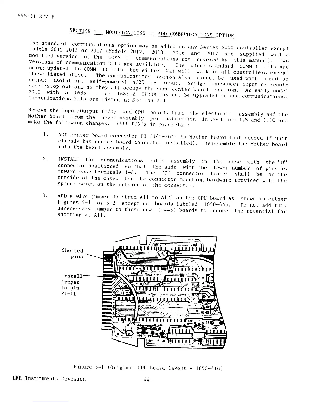
ADD
a wire
jumper
J9
(from
All
to
Al2)
Figures
5-l
or
5-2
except
on
boards
unnecessary
jumper
to
these
new
(_4U5)
shorting
at
Al
l.
on
the
CPU
board
as
shown
in
either
labeled
1650-445.
Do
not
add
this
boards
to
reduce
the
potential
for
Shorted
pins
Install
j
umper
to
pi-n
P1-11
Figure
5-1
Drvision
(0rigina1
CPII
board
layout
-
1650-416)
ltrtl!t!fft
ffiffiifur"
1:7r---t
||!iltr
-.
rjt
I
U-l
I
LFE
Instruments
-44-