EasyManua.ls Logo

LFE 2000 Series - Page 52

LFE 2000 Series
155 pages
Print Icon
To Next Page IconTo Next Page
To Previous Page IconTo Previous Page
Loading...
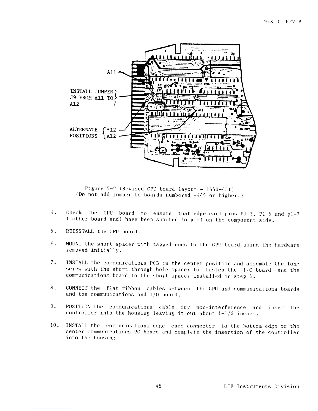
A11
INSTALL
JI]MPER
)
J9
FROM
A11
TO
}
Ar2
l
958-]1
REV B
CPU board
layout
-
1650-431)
boards
numbered
-445
or higher.)
to
ensure
that
edge
card
prns
Pl-J,
pl-5
and
pl-7
been
shorted
to
p1-l
on the
component
slde.
wittr tapped
ends
to the CPtl
board
rrsint the
hardware
ALTERNATE
POSITIONS
(
^r2
\erz
Frgure
5-2
(Revised
(Do
not
add
jumper
to
4.
Check
the
CPU
board
(mother
board
end)
have
REINSTALT,
the
CPU
board
MOUNT
the
short
spacer
removed
1nitial1y.
5.
6.
l0
INSTALL
the
communications
PCB in
the center
positron
and
assernble
the long
screw
with
the
short
through
hole spacer
to
Lasten
the
I/0 board
and the
communications
board
to the
short
spacer
installed
rn
step 6.
CONNECT
the
flat
ribbon
cables
between
the CPU
and communicatrons
boards
and the
cornmunications
and
I/0 board.
POSITION
the
communicatfons
cable
for non-interference
and insert
the
controller
into the
housing
leavlng
lt
out about
l-ll2 inches.
INSTALL
the
conmunications
edge
card
connector to the bottorn
edge of the
center
cornrnunications
PC board
and cornplete
the insertion
of the corrtroller
into
the housing.
-45-
LFE Instruments
Drvrsion