EasyManua.ls Logo

LFE 2000 Series - Page 60

LFE 2000 Series
155 pages
Print Icon
To Next Page IconTo Next Page
To Previous Page IconTo Previous Page
Loading...
958-3
1 REV
6.8
SETTING
THE
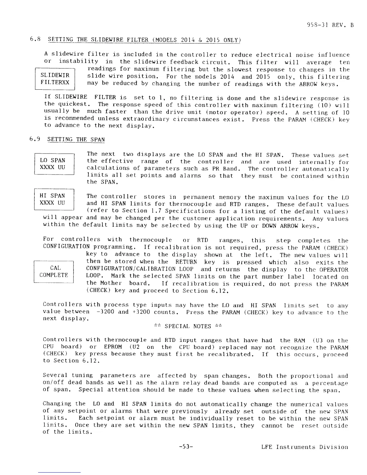
SLIDEWIRE
FILTER
(MODELS
2014
& 2OI5 ONLY)
filter
is
included
in the
controller
to
reduce electrical noise irrfluence
1lty
in
the slidewire
feedback circuit.
This
fllter will
averaBe
ten
readings
for maximum
frltering
but
the
slowest response to changes
in the
sllde
wire
position.
For
the models
2014 and
2015
only,
this filtering
may
be
reduced
by
changing
the number
of
readings
with
the
ARROW
keys.
A
slidewire
or
instabr
If
SLIDEWIRE
FILTER
1s set
to
l,
no filtering
is done
and
the slldewire
response is
the
quickest.
The
response
speed
of
this controller
with maximum
filtering
(10)
will
usually
be
much
faster
than
the
drive
unit
(notor
operator) speed.
A setting of
l0
fs
recommended
unless
extraordinary
circumstances
exlst. Press the
PARAI'{
(CHECK)
key
to
advance
to
the
next_
display.
6.9
SETTING
THE
SPAN
The
next
two
displays
are the LO
SpAN
and
the
effective
range
of the
controller
calculatlons
of
parameters
such
as
pR
Band.
ltmits
all
set
points
and alarrns
so
that
the
SPAN.
the
HI SPAN.
These values
set
and are
used
internal 1y
for
The
control
ler autonratical
ly
they
must be
contaj"ned within
wil
I appea
within
the
The
controller
stores
in
pernanent
nenory the
maximum values
for the
t,0
and
HI
SPAN
linrlts
for
thermocouple
and RTD
ranges.
These default
values
(refer
to
Section
1.7
Speciflcations
for a listing
of
the default
values)
r
and rnay
be
changed
per
the
customer
application
requirenents.
Any values
default
lrmj.ts
may
be
selected
by
using the
up or DotrlN
ARRow keys.
For
controllers
with
thermocouple
or
RTD
ranges,
this step
cornpletes
the
CONFIGURATI0N
progranming.
If recalibration
is not
required,
press
the PARAM
(CHECK)
key to
advance
to
the display
shown at
the left.
The new
values wjll
then
be
stored
when
the
RETURN
key is
presserl
whrch
also exits
the
CONFIGUMTI0N/CALIBRATI0N
L00P
and returns
the
display ro
thc OPERAT0R
L00P.
Mark the
selected
SPAN
lrmits
on
the
part
number label
located
on
the
Mother
board.
If recalibration
is requlred,
do
not
press
the PARAI'I
(CHECK)
key
and
proceed
to Section
6.12.
Controllers
with
process
type
inputs
rray have
the LO
arrd HI SPAN ltrnrts
set to any
value
between
-3200
and
+3200
counts.
Press
the PARAM
(CHECK)
key to advance to
the
next
dtsplay.
;!;'r
SpECIAL
NOTES
-*-r-
Controllers
with
therrnocouple
and
RTD lnput
rantes
that have had the [tAI'{
(U3
on the
CPU
board)
or
EPROM
(U2
on
the CPU board)
replaced nay not recotni-ze the
PARAM
(CHECK)
key
press
because
they
nust flrst
be recalibrated.
If
this
occurs,
proceed
to
Section
6. I 2.
Several
tuning
parameters
are affected
by span
changes. Both the
proporttonal
and
on/off
dead bands
as well
as the
alarm relay
dead bands
are computed as
a
percentage
of
span.
Specj-al
attention
should
be
made to these
values when
selecting the span.
Changlng
the
LO and
HI SPAN
linits do
not automatically
change the numerical values
of any
setpolut
or alarrns
that were
previously
already
set outside of the new SPAN
limits.
Each setpoint
or
alarm
must be lndivi.dually
reset to
be withrn the new SPAN
limits.
Once
they
are set within
the
new SPAN
llrnits, they cannot be
reset outstde
of
the linits.
-53-
LFE
Instruments Divlsion