EasyManua.ls Logo

LFE 2000 Series - Page 61

LFE 2000 Series
155 pages
Print Icon
To Next Page IconTo Next Page
To Previous Page IconTo Previous Page
Loading...
958-3T
REV B
6.
IO
SETTING
THE
DECIMAL
POINT
(PROCESS
RANGES
AND
MODEL
20I7
ONLY)
6.11
SETTING
THE
DISPLAY
RANGE
(PROCESS
RAryGES
AND
MODEL
20I7
ONLY)
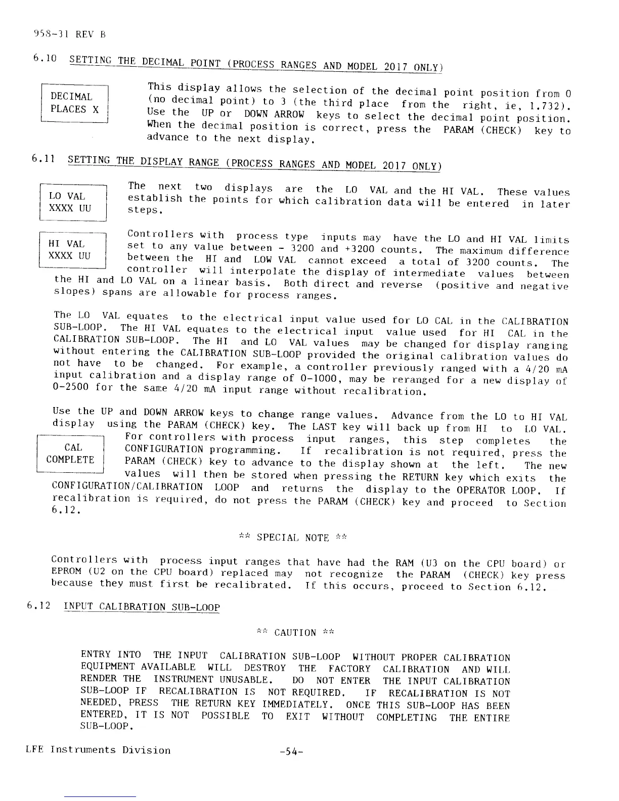
This
display
allows
the
selection
of
the
decimal
pornt
position
from
0
(no
decimal
point)
to
3
(the
third place
from
the
rieht,
i€,
r,732).
use
the
uP
or
DOWN
ARR0W
keys
to
select
the
decimal point
position.
When
the
decimal
position
is
correct,
press
the
PARAM
(CHECK)
key
to
advance
to
the
next
display.
The
next
two
displays
are
the
L0 VAL
and
establish
the
points
for
which
calibratlon
data
steps.
the
HI VAL.
These
values
will
be
entered
in
later
controllers
with process
type
inputs
may,
have
the
Lo
and
HI
vAL
llrnlts
set
to
any
value
between
-
3200
and
+3200
counts.
The
maximum
drfference
between
the
Hr
and
LOl,/
vAL
cannot
exceed
a
total
of 3200
counts.
The
controller
wlll
interpolate
the
display
of
interrnedlate
values
between
the
HI
and t,O
VAL
on
a
linear
basis.
Both
di"rect
and
reverse
(positive
and
negatrve
slopes)
spans
are
allowable
for
process
ranges.
The
L0
VAL
equates
to
the
electrical
input
value
used
for
t,O
CAL
in the
CALIBRATION
suB-LOoP'
The
HI
vAL
equates
to
the
electrical
input
value
used
for
HI
cAL
rn
the
CALIBMTT0N
suB-LooP.
The
HI
and
L0
VAL
values
may
be
changed
for
display
rantlng
wlthout
entering
the
cALTBRATI0N
suB-t,ooP
provided
the
original
calibratiorr
values
do
not
have
to
be
changed.
For
exalnple,
a
controller
previously
ranged
with
a 4/2o
nA
lnput
calibration
and
a
display
range
of 0-1000,
frdy be
reranged
for
a
nevi
di-splay
of
0-2500
for
the
sane
4/20
mA
rnput
range
without
recalibration.
use
the
uP
and
DowN
ARRot'I
keys
to
change
range
values.
Advance
from
the
L0
to
HI VAL,
display
using
the
PARM
(GHECK)
key.
The
LAST
key
will
back
up
from
HI
to
t,o vAL.
l- _ I
For
controllers
with process
input
ranges,
this
step
completes
the
| ^^.,:::_- I
CONFIGURATION
programming.
If
recalibration
is
not
requrred, press
rhe
I
uuMPLEl'E
I
PARAM
(CHECK)
key
to
advance
to
the
display
shown
at
the
left.
The
new
values
will
then
be
stored
when pressing
the
RETURN
key which
exits
the
CONFIGURATI0N/CALIBRATION
L00P
and
returns
the
display
to the
opERATOR
Loop.
if
recalibration
is
requir-ed,
do
not
press
the
pARAM
(CHECK)
key
and
proceed
to
Section
6.r2
.
6
,12
-:,rr
SPECIA[,
fr]Qff,
*:r
controllers
with process
input
ranges
that
have
had
the
EPROM
(U2
on the
CpU
board)
replaced
may
not
recognize
because
they
must
frrst
be
recalibrated.
rf
this
occurs
INPUT
CALIBMTION
SI]B-LOOP
RAM
(U3
on the
CPU
board)
or
the
PARAM
(CHECK)
key
press
,
proceed
to
Section
6.12.
-r-:'r
cAUTI0N
*,t
ENTRY
INTO
THE
INPUT
CALIBMTION
SUB-LOOP
WITHOUT
PROPER
CALIBRATION
EQUIPMENT
AVAILABLE
WILL
DESTROY
THE
FACTORY
CALIBRATION
AND WILL
RENDER
THE
INSTRUMENT
UNUSABLE.
DO
NOT
ENTER
THE
INPUT CALIBMTION
SUB_LOOP
IF
RECALIBRATION
IS
NOT
REQUIRED.
IF
RECALIBRATION
IS NOT
NEEDED,
PRESS
THE
RETURN
KEY
IMMEDIATELY.
ONCE
THIS
SUB_LOOP
HAS BEEN
ENTERED,
IT
IS NOT
POSSIBLE
TO
EXIT
WITHOUT
COMPLETING
THE
ENTIRE
SUB_LOOP.
LFE
Instruments
Division
-54-