Input
cali"bration
is required
if----
l.
Any
hardware
changes
have been made
to convert
supplied
thermocouple
rnput.
2.
Any
components
such
as
the battery.
EpROM
or
RAM
repairing
the
controller.
958-31
REV. B
from
the standard factory
have been replaced
while
3.
When
the
display
flashes
DATA LOST/PLEASE
CAL.
The
CALIBRATION
SUB-L0OP
refers
to the
procedure
for calibrating
the controller
usrng
an external precision
calibration
source.
Before starting
this calibration. one
should
see
one
of
these
two
displays:
HI
SPAN
XXXX
UU
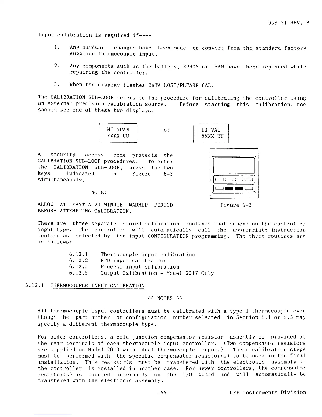
A
security
access
code
protects
the
CALIBMTI0N
SUB-L0OP
procedures.
To
enter
the
CALIBRATION
SUB-LOOP,
press
the two
keys
indicated
tn
Figure
6-3
srmultaneously.
NOTE:
-OO-
.---r-
--
ALLOIJ
AT
LEAST A
20 MINUTE
WARMUP
PERIOD
Fi.gure 5-3
BEFORE
ATTEMPTING
CALIBMTION.
There
are three
separate
stored calibration
routines that depend
on
the controller
lnput type.
The
controller
will
automati.cally call the approprj.ate
instruction
routine
as selected
by the
input CONFIGUMTION
programming.
The three routines are
as fo
I lows :
6,12.1
Thernocouple
input calibration
6,12.2
RTD input
calrbration
6,12.3
Process
input
calibration
6.12.5
0utput
Calibration
-
Model
2017
Only
6.12.
I THERMOCOUPLE
INPUT CALIBRATION
NOTES
,*.}
A11 thermocouple
input
controllers
must
be calj-brated with a type J
thermocouple
even
though the
part
number
or configuration nurnber selected in Sectron
6.1 or 6.3 may
specify a drfferent
thermocouple type.
For older controllers,
a cold
junction
compensator resistor assembly
is
provided
at
the rear terminals of each
thermocouple input controller.
(Two
compensator
resl-stors
are supplied on Model 2013
r,qith
dual thermocouple
input.)
These calibration
steps
must be
performed
with
the specific compensator resistor(s)
to be
used in the
final
installation. This
resistor(s) rnust be transfered
with the electronj-c
assembly
1f
the controller is installed
in another
case. For newer
controllers,
the
compensator
resistor(s) is rnounted internally
on
the IIO board
and
will autonratically
be
transfered with the electronic
assemblv.
-55-
LEE
Instruments
Division


 To Next Page
 Loading...