EasyManua.ls Logo

LFE 2000 Series - Page 67

LFE 2000 Series
155 pages
Print Icon
To Next Page IconTo Next Page
To Previous Page IconTo Previous Page
Loading...
958-31
REV.
B
7
.I.2
RTD
INPUT
7
.1.2.1
TEST
EQUIPMENT
Preclsion
decade
resistance
box
resfstance
range
required
(0.010).
Hrgh
impedance
dleital
vol
resistance
box
using
short
wire
connections
to
decade
errors.
AlI
wires
must
be
wlth
resolution
and
accuracy
suitable
for the
tmeter
for
voltage
measurements.
connect
the decade
low
resistance
leads
and
good
tight
connections.
Three
resrstance
box
are
requrred
to
rninirnize
lead
resistance
the
same
gauge
and
length.
Do
not use
clip
leads.
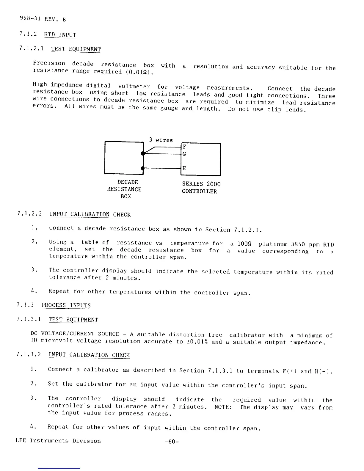
3 wires
DECADE
RNSISTANCE
BOX
SERIES
2OOO
COMROLLER
711.)
1.
7.1
7.1
?
.3
.3.1
DC
l0
,3.2
71
INPUT
CALIBRATION
CHECK
Connect
a
decade
resistance
box
as
shown
in
Section
Using
a
table
of
resistance
vs
temperature
for
a
element,
set
the
decade
resistance
box
for
a
temperature
wlthin
the
controller
span.
The
controller
display
should
indlcate
the
selected
tolerance
after
2 n1nutes.
Repeat
for other
temperat_ures
within
the
controller
PROCESS
INPUTS
7
.l ,2.1
.
l00O
platinum
3850
ppm
RTD
value
corresponding
to
a
ternperature
within
its
rated
span.
TEST
EQUIPMENT
VOLTAGE/CURRENT
SOIJRCE
-
A
suitable
drstortion
free
calibrator
wlth
a minimurn
of
mlcrovolt
voltage
resolution
accurate
to t0.01%
and
a suitable
output
impedance.
INPUT
CALIBRATION
CHECK
l. connect
a calibrator
as
descrlbed
in Section
7.1.3.1
to
terminals
F(+) and
H(-).
2.
Set the
calibrator
for
an
input
value
within
the
controllerrs
input
span.
3.
The
control
ler
dlsplay
should
lndicate
the
required
value
wlthin
the
controllerrs
rated
tolerance
after
2
minutes.
NOTE:
The
display
may
vary from
the
i-nput
value
for
process
rantes.
4.
Repeat
for
other
values
of input
withln
the
controller
span.
LFE
Instruments
Division
-60-
F
tt
H