EasyManua.ls Logo

LFE 2000 Series - Page 68

LFE 2000 Series
155 pages
Print Icon
To Next Page IconTo Next Page
To Previous Page IconTo Previous Page
Loading...
958-31 REV.
B
7
.1.4 SELF-POWERED
4/20
mA
INPUT
7
,1
.4.1 TEST
EQUTPMENT
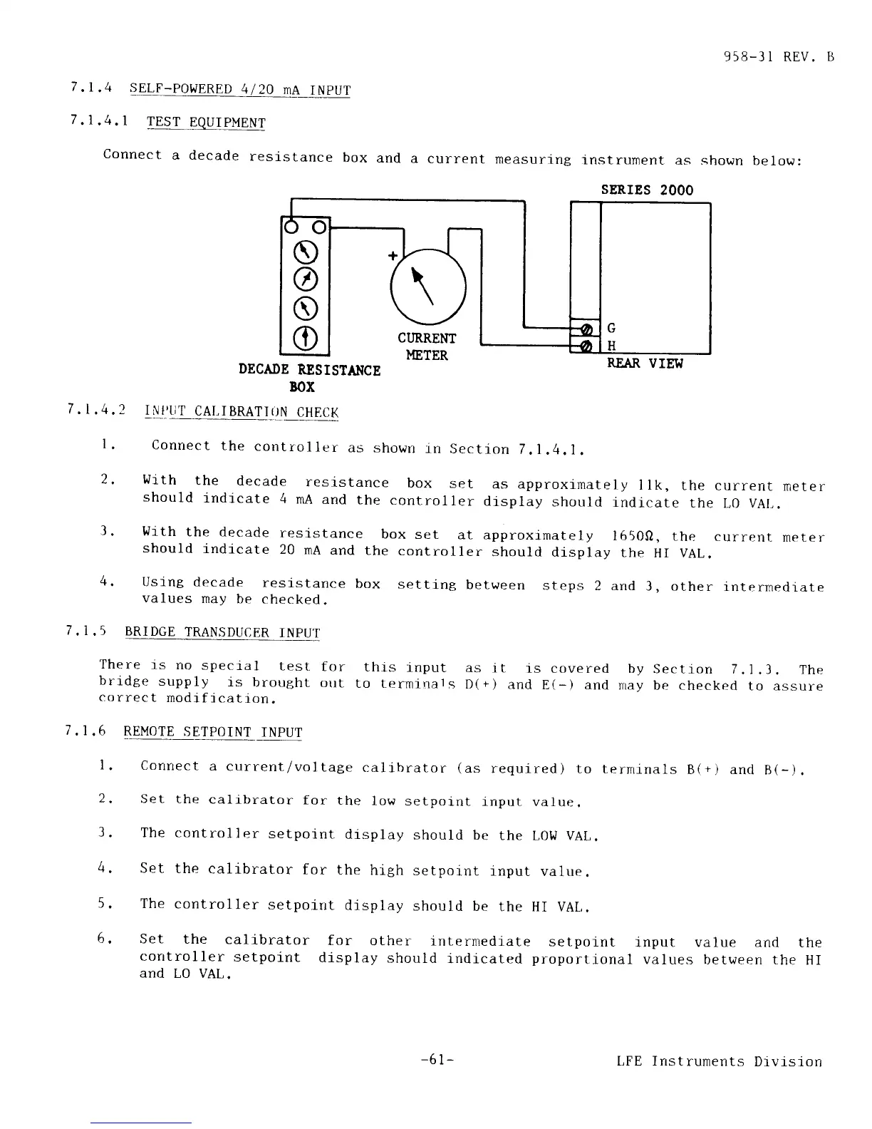
Connect
a decade
resistance
box
and
a
current
measuring
instrurnent
as shown
below:
UETER
REAR
VIEW
DECADE
RESISTAI{CE
BOX
7
.1,4.2
INIIJT
CAI,IBRATI_TJN
CHECK
I.
Connect
the
contxoller
as shown
_rn
Sectlon
7.I.4.1.
2,
wlth
the
decade
resistance
box
set
as approximateiy
llk,
the
current
neter
should
indj.cate
4
mA
and
the
controller
display
should
indj-cate
the
I-0 VAL.
3.
With
the decade
resistance
box
set
at approximately
1650O,
the
current-
meter
should
indicate
20
nA
and
the
controller
should
display
the
HI VAL.
4.
Using
decade
resistance
box
setti-ng
between
steps
2 and
3, other
interrnediate
values
rnay
be
checked.
7
.1.5
BRIDGE
TRANSDUCER
INPIJT
There
rs
no
special
test
for
thrs
input
as
it
is covered
by
Section
7.1.3.
The
brrdge
supply
ls
brought
ollt
to terminats
D(+)
and
E(-)
and may
be
checked
to assure
correct
modification.
7
,1.6 REMOTE
SETPOINT
]NPUT
l.
Conrrect
a
current-/vol
tage
calibrator
(as
required)
to terrninals
B(+) and
B(-).
2.
Set
the
calibrator
for
the
low
setpoint
input-
value.
3.
The controller
setpoint
display
should be
the
LOLr VAL.
4,
Set
the
calrbrator
for
the
high
setpoint
input
value.
5.
The
controller
setpoint
display
should
be
the
HI
VAL.
6.
Set
the
calibrator
for
other intermediate
setpoint
input value anrl
the
controller
setpoint
display
should
indicated
proportional
values
between the
HI
and
LO VAL.
SERIES
2OOO
'T
O
@
o
O
L
C
CIIRREM
I
,.6
(
-61-
LFE Instruments
Drvision