EasyManua.ls Logo

LFE 2000 Series - Page 76

LFE 2000 Series
155 pages
Print Icon
To Next Page IconTo Next Page
To Previous Page IconTo Previous Page
Loading...
6.
958-31
REV.
B
Advance
the
display
to show
the setpoint
on the bottom line.
Using
the UP
and
DOWN
arrows,
adjust
the setpoint
to the
sane value as the
process
variable
shown
on
the
top
llne.
Press
the
DISPLAY
key until
the
bottom
line
shows
OUTl XXX%
or
OUT2
XXX%.
If
the
I'{AN
lndicator
is
blinking
press
the START/STOP
key to turn the
irrdrcator
off.
Adjust
the
calibration
source
until the
Display
shows OUTI
1OO%, After
an
approximate
l5 second
time
delay
(will
vary
depending on the cycle
time settr.ng)
the
external
lanp
aud
the
display OUTl or
0UT2
indicators should
illumrnate.
9.
Adjust
the
calibration
source
until the
display
shows 0UTl
5O7"
or 0UT2 50%.
Note
that
the
output
rndicators
and the external
load lamps
cycle with au
approximate
5O%
duty
cycle
and tha the time
base
is equal
to the
cycle tj-me.
10.
If the
second
SSR
output
is
proporti-onrng
action,
repeat
This
verif
ies
the .S.SR
circult
outputs.
Turn
of f
the
load
lamp
circuitry.
7
,2.5
DC
TRIGGER
OUTPUT
TEST
the
procedure
above.
AC
power
and remove the
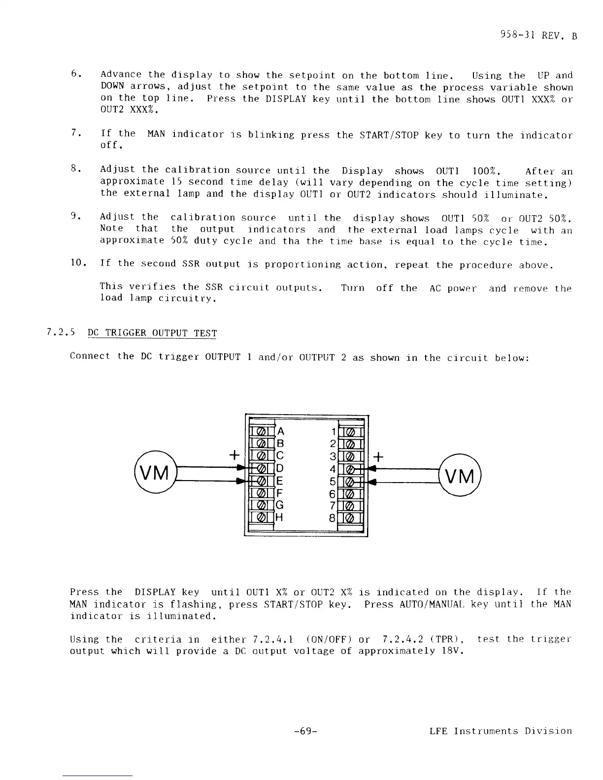
Connect
the
DC
trigger
OUTPUT
I
and/or
OUTPIJT 2
as shown
in the circuit
below;
Press
the
DISPLAY
key until OUTI X% or 0UT2 Xi{ ls indicated on
the display. If
the
MAN
indicator is flashing,
press
START/STOP key. Press
AUT0/MANUAL
key until
the MAN
indicator
1s illumi-nated.
UsinB the
criteria rn either 7,2,4,1
(0N/0FF)
or
7.2.4,2
(TPR),
output whrch will
provide
a DC output
voltage of approximately
18V.
test
the trrgger
A1
B2
C3
D4
E5
F6
G7
H8
-69-
LFE Instruments
Drvtston