EasyManua.ls Logo

LFE 2000 Series - Page 77

LFE 2000 Series
155 pages
Print Icon
To Next Page IconTo Next Page
To Previous Page IconTo Previous Page
Loading...
958-31
REV.
B
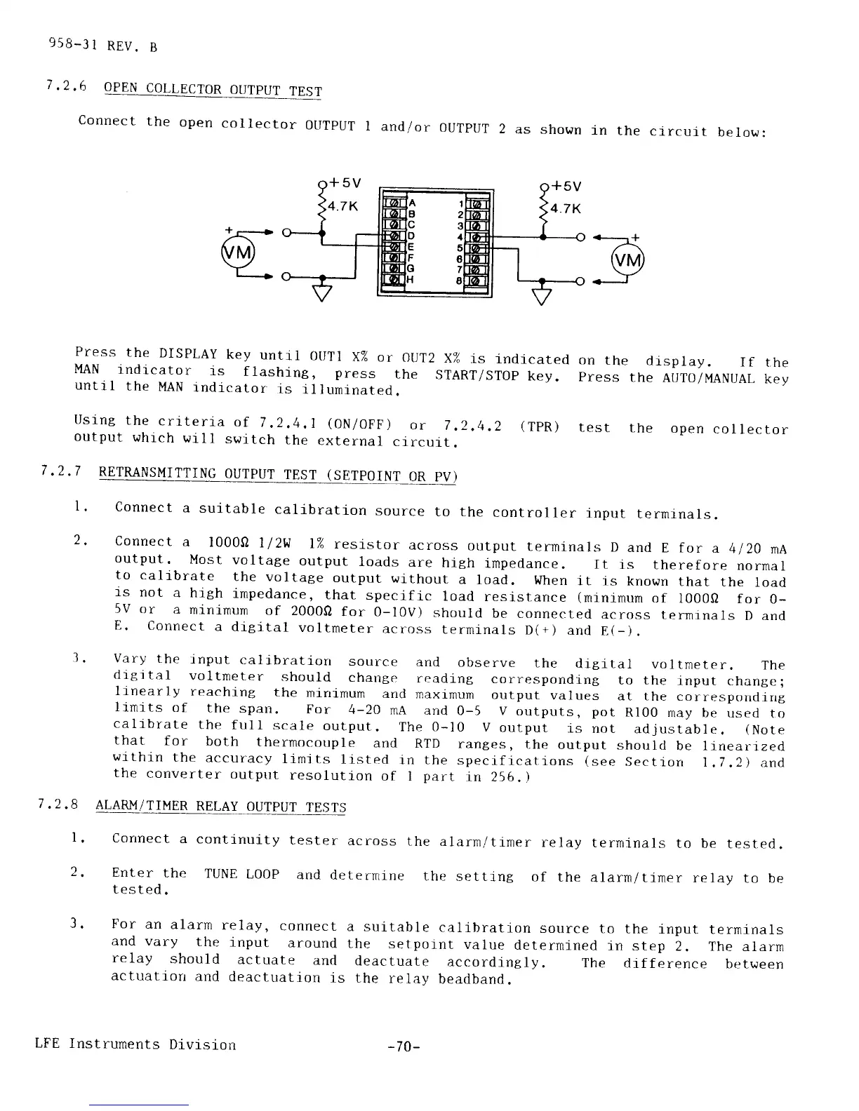
7.2.6
OPEN
COLLECTOR
OUTPUT
TEST
Connect
the
open
collector
OUTPUT
I
andlor
OUTPUT
2
as
shown
in
the
circuit
below:
Press
the
DISpLAy
key
untii
0UTl
X%
or
OUT2
MAN
lndicator
is
flashing,
press
the
untrl
the
MAN
indicator
is
illuminated.
on
the
display.
If
the
Press
the
AUTO/MANUAL
kev
X%
is
indicated
START/STOP
key.
Using
the
criteria
of
7
.2,4,1
(ON/OFF)
or
7
,2.4.2
output
which
will
switch
the
external
clrcuit.
7,2.7
RETRANSMiTTING
OUTPUT
TEST
(SETPOINT
OR
pV)
l.
2,
7.2.8
l.
z.
1
(TPR)
test
the
open
collector
Connect
a
suitable
callbration
source
to the
controller
input
terminals.
connect
a
l000fl
1/2w
l%
resistor
across
output
terminals
D
and
E for
a
4120
nA
output.
Most
voltage
output
loads
are
high
impedance.
It
is
therefore
normal
to calj-brate
the
voltage
output
without
a
load.
When
it 1s
known
that
the
load
ts
not
a hrgh
impedance,
that
specrfic
load
resistance
(minimum
of
l000fl
for
0_
5V
or
a
minirnurn
of
20000
for 0-l0V)
should
be connected
across
termrnals
D and
E.
connect
a
dieltal
voltmeter
across
terminals
D(+)
and
E(-).
Vary
the
input
calibratiorr
source
and
observe
the
drgltal
voltmeter.
The
digjtal
voltmeter
should
change
reading
corresponding
to the
lnput
change;
linearly
reaching
the
mini-mum
and
maximum
output
values
at the
correspondlrrg
limits
of
the spau.
For
4-20
mA
and
0-5 v
outputs,
pot
Rl00
may be
used
to
calrbrate
the frrll
scale
output.
The 0-10
V
output
is
not
adjustable.
(Note
that
for
both
thermocouple
and
RTD
rantes,
the
output
shoulcl
be linearrzed
wrthin
the
accuracy
limjts
llsted
in the
specificatlons
(see
Sectron
t.l.2)
and
the
converter
output
resolution
of
I
part
1n
256.)
AIARM/TIMER
RELAY
OUTPUT
TESTS
Corrnect
a
continuity
tester
across
the
alarm/timer
relay
terminals
to be
tested.
Enter
the
TUNE
L0oP
and
determine
the
settj.ng
of
the
alarmltimer
relay
to be
tested.
For
an
alarm
relay,
connect
a suitable
calibration
source
to
the
input
terminals
and vary
the
input
around
the
setpornt
value
determined
in
step
2. The
alarm
relay
should
actuate
and
deactuate
accordingly.
The
difference
between
actuatiorr
and
deactuation
is the
relay
beadband.
LFE Instruments
Division
-
70-