Do you have a question about the LG 14HQ701G-B and is the answer not in the manual?
A general introduction to the detector's functionality and features.
Visual and textual identification of standard accessories included with the detector.
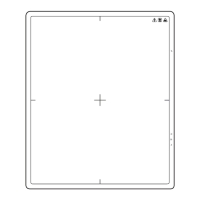
Details the front and back views of the detector, labeling its parts and identifying key features.
Illustrates and labels the components and buttons located on the side of the detector.
Describes how to turn the detector power on and off using the power button with specific press-and-hold durations.
Explains how to use the connection button to switch between Ethernet, Station, and AP modes.
Details the use of the Fn button for menu navigation and changing function settings.
Outlines the steps to restore the detector to factory default settings by pressing specific buttons simultaneously.
Explains the meaning of the Power LED indicator for power and battery status (off, on, low battery).
Details the status indicated by the Wired/Wireless LED for connection modes like Ethernet and Wireless.
Describes the brief illumination of the Fn LED when the function switch is used to change settings.
Shows how connection modes (Ethernet, Station, AP) and related information are represented on the OLED indicator.
Explains the information displayed on OLED for dynamic status, video acquisition, and auto-save functions.
Describes the LED patterns for battery levels (0-30%, 30-70%, 70-99%, 100%) and charging status on the charger.
Provides important notes about battery type, charging time, and troubleshooting connection errors.
Explains the status indicated by the LED lights on the control box for power, Ethernet, readiness, and exposure.
Describes the purpose and connection details for each port on the control box, including DXD, Ethernet, and Sync.
Outlines restrictions on detector functionality and data collection during the hot-swap process.
Provides advice regarding adhesive strength, secure fixing, and proper storage with the cable holder.
Lists detailed technical specifications of the detector, including dimensions, performance metrics, and data transmission.
Details the specific X-ray parameters tested for different sensor types for optimal imaging.
Specifies environmental conditions for operation and the necessary PC system requirements.
Outlines specifications for the grid component and the detector's battery pack.
Lists specifications for the LG Battery Charger and its power adapter, including model, size, and input/output.
Details the model, size, weight, input, and output specifications for the LG Control Box.
Lists the main cable, LAN cable, power cord, and trigger cable with their lengths and quantities.
Details the frequency range and output power for the wireless LAN module (IEEE 802.11a/b/g/n/ac).
Guides the user through the process of launching the installation file and completing the software setup.
Explains the steps for removing the calibration software from the PC, via Control Panel or installation file.
Describes how to connect the X-ray generator to the detector, including auto and manual trigger modes.
Details the wired and wireless connection methods between the detector and a PC.
Explains how to use the wired/wireless connection button to switch between Ethernet, Station, and AP modes.
Details the function of each pin on the trigger cable connector for proper connection to the control box and X-ray generator.
Shows the wiring diagram for connecting the X-ray generator to the control box via the trigger cable.
Illustrates the timing sequence of signals (EXP_REQ, EXP_ACK) for the trigger cable operation.
Shows the connection setup for the detector to PC in wired Auto Mode.
Shows the connection setup for the detector to PC in wired Manual Mode.
Guides users through setting up IP addresses, subnet mask, and default gateway on the PC for wired connectivity.
Details how to launch the calibration software, enter the detector's IP, and perform a ping test for connection verification.
Shows the connection setup for the detector to PC in wireless Station Mode using an external AP.
Shows the connection setup for the detector to PC in wireless AP Mode using the detector's internal AP.
Illustrates the connection setup for manual mode wireless communication between detector and PC.
Outlines the factory default wireless settings for Station and AP modes, including SSID.
Explains the steps to connect in Station mode and AP mode, including PC configuration if ping test fails.
| Brand | LG |
|---|---|
| Model | 14HQ701G-B |
| Category | Security Sensors |
| Language | English |