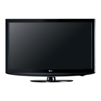
FRONT (IR and POWER LED) SECTIONFRONT (IR and POWER LED) SECTION
The IR board (located on the bottom left as viewed from the rear) contains the IR (Infrared) Remote
Sensor and Power LEDs. This board also connects to the Key Board.
The IR board receives it operating B+ via J1 pin 6 (STBY 3.5V).
The IR (Infrared) remote receiver can be measured (2V) at pin 9 of connector J1 or P2401 on the Main
board in Stand-By. During run pin 9 reads (1.98V).
nes,
(Key 1 pin 4 and Key 2 pin 5). Arriving at P2401 pins 4 and 5 on the Main Board.
Then to the Microprocessor Pins A4 and B4.
November LCD TV 32LD350
61

 Loading...