Copyright © 2007 LG Electronics. Inc. All right reserved.
Only for training and service purposes
LGE Internal Use Only
3. PSU(Power Supply Unit) Voltage
Adjustment
(Va, Vs Voltage Adjustment)
Adjust the voltages Va and Vs supplied from the PSU to the
module within the specified range of each module to supply
the stable power
3-1. Test Equipment
(1) D.M.M 1EA
(2) Voltage adjustment bar
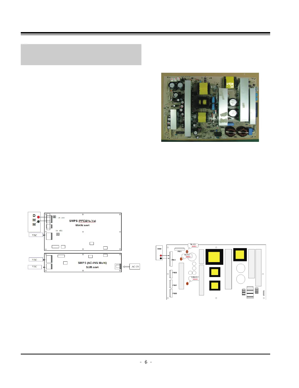
3-2. Adjustment(60”)
(1) Va Voltage Adjustment
1) Connect + terminal of D.M.M to Va pin of P812 and
connect – terminal to GND pin of P812.
2) Adjust VR901 voltage to match that of the label on the
Top/Right of the panel. (Deviation : ±0.5V)
(2) Vs Voltage Adjustment
1) Connect + terminal of D.M.M to Vs pin of P812 and
connect – terminal to GND pin of P812.
2) Adjust VR951 voltage to match that of the label on the
Top/Right of the panel. (Deviation : ±0.5V)
3-3. Adjustment (50”)
(1) Va Adjustment
1) Connect + terminal of D.M.M to Va pin of P12 and
connect – terminal to GND pin of P12.
2) Adjust VR951 voltage to match that of the label on the
Top/Right of the panel. (Deviation : ±0.5V)
(2) Vs Adjustment
1) Connect + terminal of D.M.M to Vs pin of P12 and
connect – terminal to GND pin of P12.
2) Adjust VR901 voltage to match that of the label on the
Top/Right of the panel. (Deviation : ±0.5V)
3-4. Adjustment(42”)
(1) Va Voltage Adjustment
1) Connect + terminal of D.M.M to Va pin of P812 and
connect – terminal to GND pin of P812.
2) Adjust VR901 voltage to match that of the label on the
Top/Right of the panel. (Deviation : ±0.5V)
(2) Vs Voltage Adjustment
1) Connect + terminal of D.M.M to Vs pin of P812 and
connect – terminal to GND pin of P812.
2) Adjust VR951 voltage to match that of the label on the
Top/Right of the panel. (Deviation : ±0.5V)
ADJUSTMENT INSTRUCTIONS
Each PCB assembly must be checked by check JIG set.
(Because power PCB Assembly damages to PDP Module,
especially be careful)
Connection Diagram of Power Adjustment for Measuring
(Power Board): 60”
Connection Diagram of Power Adjustment for Measuring
(Power Board): 50”
Connection Diagram of Power Adjustment for Measuring
(Power Board): 42”(EAY32808901)