Do you have a question about the LG A6UW406FA0 and is the answer not in the manual?
Explanation of the model number structure for indoor units.
Explanation of the model number structure for outdoor units.
Details on model number nomenclature for panel types.
Classification of indoor units by type and capacity, and outdoor unit specs.
Crucial safety guidelines for installing the unit.
Further safety instructions regarding power cables and installation area.
Safety instructions on water, flammable gas, and storm conditions.
Safety instructions on product operation, cleaning, and securing the outdoor unit.
Safety guidelines for product installation location and usage.
Safety instructions for handling filters, batteries, and cleaning.
Physical dimensions and installation plate details for indoor units.
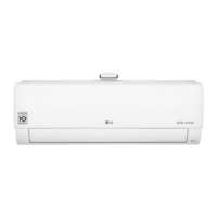
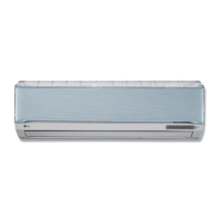
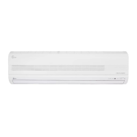
Dimensions for split type indoor units.
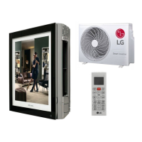
Dimensions for Art Cool type indoor units.
Dimensions for Art Cool Deluxe type indoor units.
Dimensions for duct type indoor units.
Dimensions for CVT type indoor units.
Dimensions and connection details for CST Type TC,TC1 units.
Dimensions for CST Type TE(1) units.
Dimensions for CST Type TF units.
Dimensions for CST Type TH units.
Dimensions for CST Type TD units.
Physical dimensions for various outdoor unit models.
Detailed specifications for Wall Mounted indoor units.
Model type classification for indoor units.
Specifications for ART COOL Mirror and ART COOL DELUXE indoor units.
Specifications for ART COOL DELUXE and ART COOL indoor units.
Specifications for Ceiling Cassette - 1 way and 4 way, and Concealed Duct units.
Specifications for Ceiling Cassette - 1 way indoor units.
Specifications for CST and Concealed Duct units.
Specifications for Ceiling Concealed Duct and Ceiling & Floor units.
Specifications for Ceiling Concealed Duct - Low Static units.
Specifications for multiple piping outdoor units.
Further specifications for multiple piping outdoor units.
Specifications for distributor type outdoor units.
Specifications and notes for LG Branch Distributors.
Guidance on choosing the optimal location for indoor units.
Installation location considerations for split type indoor units.
Installation location considerations for Art Cool type indoor units.
Installation location considerations for Art Cool Deluxe units.
Installation requirements for duct type indoor units.
Installation location considerations for CST type indoor units.
Installation location considerations for CVT type indoor units.
Step-by-step guide for installing room type indoor units.
Disassembly and installation steps for Art Cool type indoor units.
Guide to using the installation map and fixing the indoor unit.
Instructions for drilling wall holes for piping.
Installation steps for Art Cool Deluxe Type indoor units.
Installation instructions for Duct Type indoor units (BH chassis).
Installation of the main unit for BT chassis.
Installation instructions for BP chassis units.
Installation instructions for B1, B2 chassis units.
Steps for preparing pipes, including cutting, removing burrs, and flaring.
Detailed steps for connecting piping for split type indoor units.
Instructions for routing and wrapping pipes for right rear piping.
Final piping connections and insulation steps.
Piping and drain hose connection for Art Cool Type units.
Steps for assembling the front panel and connecting wires.
Piping connection steps for Art Cool Deluxe Type indoor units.
Instructions for routing and wrapping pipes for left rear piping.
Final piping and insulation steps for left rear routing.
CAUTION regarding tubing bending and pipe damage.
Indoor unit installation for duct type units, including suspension bolts.
Installation on the ceiling for CVT type units (VB chassis).
Securing installation plates and adjusting unit level for ceiling mounting.
Installation on the wall for VE chassis units.
Steps for mounting anchor nuts and bolts for ceiling installation.
Instructions for drilling holes in the wall for piping.
Importance of unit declination for proper drainage.
Steps for securing the unit to installation plates and attaching components.
Wall installation steps, including drilling and securing plates.
Securing the indoor unit to the installation plate and attaching parts.
Floor installation steps, including mounting brackets and piping.
Ceiling opening dimensions and hanging bolt locations for TC, TC1 chassis.
Indoor unit installation steps, including hanging bolts and piping hole drilling.
Ceiling opening dimensions and installation for TE(1)/TF/TH/TD chassis.
Indoor unit installation details, including hanging bolts and piping hole drilling.
Steps for installing a wired remote controller.
Wiring diagram for remote controller connection.
Instructions for inserting batteries into the remote controller.
Detailed procedure for connecting pipes to the outdoor unit.
Electrical specifications for indoor units.
Electrical safety precautions regarding power supply and wiring.
Steps to check drainage and pipe formation for split type indoor units.
Steps to check drainage for Art Cool type indoor units.
Checking drainage and drain piping for Art Cool Deluxe units.
Checking drainage and drain piping for Convertible Type units.
CAUTION for gradient of unit and drain piping for Duct Type.
Drain piping instructions and drain test for CST Type indoor units.
Allowable piping length and extra charge calculation for multi-piping systems.
Calculating additional refrigerant charge based on pipe length.
Maximum allowable level and piping length for distributor type systems.
Piping length details for the A4UW306FA1 distributor type.
Calculation of additional refrigerant charge based on pipe length.
Specifications for piping connections based on indoor unit type.
Importance and installation of traps in refrigerant piping.
Details on the standard Y-Branch accessory.
Test running procedures and evaluation for specific indoor unit types.
Operation procedures for CVT type units.
Precautions in test run and installation completion checks.
Diagrams illustrating system layout and piping configurations.
Precautions for selecting the location of the branch distributor.
General installation guidelines for suspension or wall mounting.
Procedure for ceiling-suspended installation of the main unit.
Procedure for wall-mounted installation of the main unit.
Steps for connecting pipes and insulating them.
How to properly close unoccupied piping sockets.
Wiring connections for systems with up to 3 rooms.
Overview of the main unit functions and indicators.
Details on how the cooling mode operates.
Explanation of the soft dry operation mode.
Details on how the heating mode operates.
How defrost control works during heating operation.
Explanation of the fuzzy operation logic.
Fuzzy operation logic for dehumidification and heating modes.
How to select airflow speed using the remote control.
Operation of the sleep timer function.
How the chaos swing mode operates.
Details on the chaos natural wind mode operation.
Operation of the jet cool mode.
How auto restart operates after power failure.
How to operate the unit using forced operation mode.
Explanation of buzzer sounds during operation.
Overview of functions for split type indoor units.
Overview of functions for Art Cool type indoor units.
Functionality of the Art Cool Deluxe Type remote controller.
Functionality of the Duct Type remote controller.
Functionality of the CST Type remote controller.
Functionality of the Convertible Type remote control.
Overview of outdoor unit functions and algorithms.
Explanation of the operation modes available via remote control.
Features and functions of the simple central control system.
Description of the parts and functions of the central control unit.
Pictorial view and connection diagram for electrical wiring.
Connection diagram for simple central control systems.
Connection details for multiple simple central control units.
Setting method for PI485 interface in LG Aircon Network.
Method for setting the address of indoor units using wired or wireless remotes.
How to monitor the set address of indoor units.
General cautions regarding installation locations.
Steps for installing the central control unit.
How to connect the wiring for the central control unit.
Setting the group number using the rotary switch.
Setting the DIP switch for master/slave mode.
Optional accessory parts for central control.
Summary of the Deluxe Central Control system.
Key characteristics of the Deluxe Central Control system.
Ease of use and intuitive interface of the Deluxe Central Control.
Features for schedule management and energy saving.
Stability and power failure backup features.
Mobility features of the Deluxe Central control.
Ease of physical installation for the system.
Data storage and backup capabilities.
System scalability and upgrade capabilities.
Key functions of the Deluxe Central Control system.
General monitoring and control of air conditioners.
Checking the real-time status of all air conditioners.
Managing air conditioners through grouping and setup.
Setting weekly schedules for air conditioner operation.
Key specifications of the control system, CNU, and PI485.
General safety caution for disassembly.
Steps for removing the grille and internal components of split type units.
Procedure for removing the control box.
Procedure for removing the discharge grille.
Procedure for removing the evaporator.
Procedure for removing the cross-flow fan and motor.
Disassembly steps for Art Cool Type indoor units.
Procedure for removing the evaporator.
Steps before removing the turbo fan.
Procedure for removing the motor cover.
Disassembly steps for Art Cool Deluxe Type indoor units.
Disassembly steps for Art Cool Deluxe Type SE indoor units.
Procedure for removing the control box.
Procedure for removing the discharge grille.
Procedure for removing the evaporator.
Procedure for removing the motor cover.
Procedure for removing the cross-flow fan.
Disassembly steps for CVT Type VB chassis units.
Disassembly steps for VE chassis units.
Procedure for removing the control box.
Procedure for removing the discharge grille.
Procedure for removing the evaporator.
Procedure for removing the motor cover.
Procedure for removing the cross-flow fan.
Steps for removing air guide, crossflow fan, and motor.
Procedure for removing the control box assembly.
Procedure for removing the front panel.
Procedure for removing the diffuser assembly.
Procedure for removing the display PCB assembly.
Steps for removing vanes and step motor.
Procedure for removing the drain pan assembly.
Procedure for removing the evaporator assembly.
Schematic diagram of the electronic control device.
Schematic diagram for the indoor unit.
Schematic diagram for Split Type indoor units.
Schematic diagram for Art Cool Type indoor units.
Schematic diagram for Art Cool Deluxe Type A/C MOTOR.
Schematic diagram for Art Cool Deluxe Type BLDC MOTOR.
Schematic diagram for Duct Type indoor units.
Schematic diagram for Slim Duct B1, B2 chassis.
Schematic diagram for Convertible Type indoor units.
Schematic of the VE chassis AC part.
Schematic diagram for VB chassis.
Schematic diagram for outdoor units.
Schematic diagram for the A6UW406FA0 outdoor unit.
Outdoor unit schematic details for specific models.
Schematic diagram for the central control unit.
Wiring diagram for Room Type indoor units.
Wiring diagram for Art Cool Type indoor units.
Wiring diagram for Room Type S4/S5 chassis units.
Wiring diagram for Duct Type BH/BP chassis units.
Wiring diagrams for Art Cool Deluxe Type A/C and BLDC Motors.
Wiring diagrams for Duct Type BH/BP chassis.
Wiring diagrams for CVT Type VE chassis.
Wiring diagrams for CVT Type VB chassis.
Wiring diagrams for CST Type TE/TF/TD chassis.
Wiring diagrams for CST Type TE1 chassis.
Wiring diagrams for CST Type TH chassis.
Wiring diagram for CST Type TC chassis.
Wiring diagram for CST Type TC1 chassis.
Wiring diagram for Art Cool Mirror SE units.
Wiring diagram for Slim Duct B1, B2 chassis.
Wiring diagrams for various outdoor unit models.
Wiring diagram for A2UW146FA0, A2UW146FA1 outdoor units.
Wiring diagram for A3UW186FA0, A3UW186FA1 outdoor units.
Wiring diagram for A4UW246FA0 outdoor unit.
Wiring diagram for A7UW486FA0, A8UW586FA0 outdoor units.
Wiring diagram for A2UW146FA2, A2UW166FA0/1 outdoor units.
Component locations for indoor units.
Component locations for split type indoor units.
Component locations for the DC part of the indoor unit.
Component locations for the AC part of the indoor unit.
Component locations for Art Cool Type indoor units (Top and Bottom views).
Component locations for Art Cool Deluxe Type A/C MOTOR.
Component locations for Art Cool Deluxe Type BLDC MOTOR.
Component locations for Duct Type indoor units (BH/BG and BP chassis).
Component layout for low static Duct Type BT, BT1 chassis.
Component layout for low static Duct Type B1, B2 chassis.
Component locations for Cassette Type - 1 way (TC chassis).
Component locations for 1-way Cassette TC1 chassis.
Component locations for 4-way Cassette TE/TF/TD chassis.
Component locations for 4-way Cassette TE1/TH chassis.
Component locations for Convertible Type indoor units.
Component locations for VE chassis AC and DC parts.
Component locations for VB chassis.
Component locations for VB chassis (Top and Bottom views).
Component locations for display assemblies.
Component locations for Display Assembly of Split Type.
Component locations for Display Assembly of Convertible Type.
Component locations for VE chassis display.
Component locations for VB chassis display.
Component locations for Art Cool Type display.
Component locations for Art Cool Deluxe Type display.
Component locations for Art Cool Mirror display.
Component locations for outdoor units.
Component layout on the component side of the outdoor PCB.
Component layout on the solder side of the outdoor PCB.
Component locations for the central control PCB.
Component layout on the top view of the central control PCB.
Component layout on the bottom view of the central control PCB.
Component locations for the SUB P.W.B ASSEMBLY.
Component locations for Art Cool Type SUB P.W.B.
Refrigeration cycle diagram for A2UW146FA0/1/2, A2UW166FA0/1, etc.
Refrigeration cycle diagram for A3UW246FA0, A4UW246FA0 models.
Refrigeration cycle diagram for A4UW306FA0 model.
Refrigeration cycle diagram for A4UW306FA1 model.
Refrigeration cycle diagram for A6UW406FA0 model.
Refrigeration cycle diagram for A7UW486FA0, A8UW566FA0 models.
Refrigeration cycle diagram for BD Units.
Explanation of indoor and outdoor error indicators.
List of indoor unit error codes and their meanings.
Error codes and descriptions for outdoor unit self-diagnosis.
Analysis of common refrigeration cycle troubles.
Troubleshooting steps for product not operating at all.
Troubleshooting steps when the remote controller is not working.
Troubleshooting steps when compressor or outdoor fan do not operate.
Troubleshooting steps when the indoor fan does not operate.
Troubleshooting steps when the louver does not operate.
Explanation of indoor error indicators.
List of indoor unit error codes and their meanings.
Outdoor error codes and their meanings, including LED indicators.
Further outdoor unit error codes and their meanings.
Troubleshooting steps for specific error codes related to sensors.
Troubleshooting steps for communication errors.
Troubleshooting steps for drain pump or float switch issues.
Troubleshooting steps for communication errors between indoor and outdoor units.
Troubleshooting steps for DC Peak errors, including IPM and compressor checks.
Troubleshooting steps for C/T internal circuit or current errors.
Troubleshooting steps for DC Link voltage errors.
Troubleshooting steps for press switch and input voltage errors.
Troubleshooting steps for compressor position and PSC fault errors.
Troubleshooting steps for pipe temperature errors.
Troubleshooting steps for sensor errors (pipe, air, heat sink).
Troubleshooting steps for over capacity and EEPROM errors.
Troubleshooting steps for high temperature errors in condenser and heat sink.
Shaft positions and service ports for 3-way valves (liquid and gas sides).
Procedure for pumping down the system using 3-way valves.
Procedure for evacuating the system (removing air and moisture).
Procedure for charging the system with refrigerant.
Exploded view of the indoor unit for SQ/SR chassis.
Replacement parts list for SQ, SR chassis indoor units.
Exploded view of the ST chassis indoor unit.
Replacement parts list for ST chassis indoor units.
Exploded view of S4, S5 chassis indoor units.
Replacement parts list for S4, S5 chassis indoor units.
Exploded view of SP1 chassis indoor units (Art Cool Type).
Replacement parts list for Art Cool Deluxe Type A/C Motor units.
Exploded view of Art Cool Deluxe Type SU, SZ, S3 chassis (A/C Motor).
Replacement parts list for Art Cool Deluxe Type BLDC units.
Exploded view of Art Cool Deluxe Type SU, SZ, S3 chassis (BLDC Motor).
Replacement parts list for Art Cool Deluxe Type BLDC units.
Exploded view of Convertible Type VE chassis units.
Replacement parts list for Convertible Type VE chassis units.
Exploded view of Duct Type Low Static B1 chassis.
Replacement parts list for Duct Type Low Static B1 chassis.
Exploded view of Duct Type Low Static B2 chassis.
Replacement parts list for Duct Type Low Static B2 chassis.
Exploded view of Duct Type High Static chassis.
Replacement parts list for Duct Type High Static chassis.
Exploded view of Duct Type Low Static BT, BT1 chassis.
Replacement parts list for Duct Type Low Static chassis.
Exploded view of Built in Duct type BP chassis.
Replacement parts list for Built in Duct Type BP chassis.
Exploded view of Cassette Type 1 way TC1 chassis.
Replacement parts list for Cassette Type 1 way units.
Exploded view of Cassette Type 1 way TC chassis.
Replacement parts list for Cassette Type 1 way units.
Exploded view of Cassette Type 4 way TE(1) chassis.
Exploded view of Cassette Type 4 way chassis components.
Replacement parts list for Cassette Type 4 way TE(1) units.
Exploded view of Cassette Type 4 way TF chassis.
Exploded view of Cassette Type 4 way chassis components.
Replacement parts list for Cassette Type 4 way TF units.
Exploded view of Cassette Type 4 way TH chassis.
Exploded view of Cassette Type 4 way chassis components.
Replacement parts list for Cassette Type 4 way TH chassis.
Exploded view of Cassette Type 4 way TD chassis.
Exploded view of Cassette Type 4 way chassis components.
Replacement parts list for Cassette Type 4 way TD chassis.
Exploded view of Convertible Type VE chassis units.
Replacement parts list for Convertible Type VE chassis units.
Exploded view of Convertible Type VB chassis units.
Replacement parts list for Convertible Type VB chassis units.
Exploded view of outdoor units.
Exploded view of specific outdoor unit models.
Exploded view of specific outdoor unit models.
Exploded view of specific outdoor unit models.
Replacement parts list for single compressor inverter outdoor units.
Detailed parts list for single compressor inverter outdoor units.
Exploded view of specific outdoor unit models.
Replacement parts list for TPS Inverter outdoor units.
Exploded view of A4UW306FA0, A4UW306FA1 outdoor units.
Replacement parts list for TPS Inverter outdoor units.
Exploded view of A6UW406FA0 outdoor unit.
Replacement parts list for TPS Inverter outdoor units.
| Brand | LG |
|---|---|
| Model | A6UW406FA0 |
| Category | Air Conditioner |
| Language | English |