This document is an installation manual for an LG Ceiling Concealed Duct Air Conditioner. It provides detailed instructions for installation, wiring, and initial setup, along with safety guidelines and tips for energy saving.
Function Description
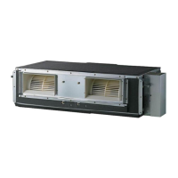
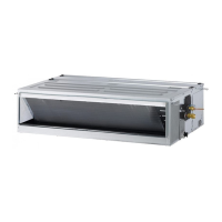
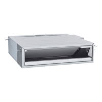
The LG Ceiling Concealed Duct Air Conditioner is designed to provide cooling and dehumidifying functions for indoor spaces. It is a duct-type unit, meaning it is installed above the ceiling and distributes conditioned air through a duct system. The unit is controlled via a wired remote controller, which also houses the room temperature sensor. The manual covers various installer settings to optimize the unit's performance based on installation conditions and user preferences.
Key functions include:
- Cooling/Dehumidifying: The primary function of the air conditioner.
- Remote Control: Operates via a wired remote controller, which also serves as the room temperature sensor.
- Group Control: Allows multiple indoor units to be controlled by a single wired remote controller, or a single indoor unit by multiple wired remote controllers.
- Installer Settings: A suite of configurable options accessible via the remote controller to fine-tune the unit's operation, including:
- Test Run Mode: A diagnostic mode to confirm proper installation by operating the unit under specific conditions (cooling, strong wind, compressor on) without room temperature control.
- Address Setting of Central Control: Configures the network address for the indoor unit when connected to a central controller, allowing the central controller to recognize and manage it.
- E.S.P. (External Static Pressure) Value: Adjusts the strength of the wind for each fan speed level, crucial for duct-type units to ensure proper airflow. Incorrect settings can lead to malfunction.
- Thermistor Selection: Allows selection of the temperature sensor used to judge room temperature (remote controller, indoor unit, or 2TH sensor).
- Remote Controller Master/Slave Setup: Configures the role of remote controllers in group control or multi-remote controller setups.
- Celsius / Fahrenheit Switching: Changes the temperature display unit on the remote controller.
- Static Pressure Step Setting: Divides the product's static pressure into 11 steps for fine-tuned adjustment, applicable only to duct-type units.
- DIP Switch Settings: Physical switches on the indoor PCB for configuring advanced functions like Group Control (Master/Slave), Dry Contact Mode (Wired/Wireless remote controller, Manual/Auto operation), and Fan continuous operation.
Important Technical Specifications
The manual provides several technical specifications, primarily related to installation and wiring:
Drain Piping:
- Slope: Must have a downward inclination of 1/100 to 1/50 to ensure proper water drainage.
- Drain Port Diameter: The outside diameter of the drain connection on the indoor unit is 32 mm.
- Piping Material: Polyvinyl chloride pipe VP-25 and pipe fittings are recommended.
- Thermal Insulation: Drain piping must be thermally insulated with polyethylene foam, at least 8 mm thick.
- Drain Raising Pipes: If used, should be at a right angle to the indoor unit and no more than 300 mm from the unit.
- U-Trap/P-Trap: Recommended to prevent water leakage caused by blocked intake air filters. Applied U-Trap dimensions are: A ≥ 70 mm, B ≥ 2C, C ≥ 2 x SP (where SP is External Pressure in mmAq).
Refrigerant Piping Insulation:
- Minimum Thickness: 19 mm for connecting pipes.
- Standard Conditions (30 °C, 85% RH):
- Liquid piping (6.35 mm, 9.52 mm): 9 mm insulation.
- Liquid piping (12.7~44.45 mm): 13 mm insulation.
- Gas piping (6.35~31.75 mm): 13 mm insulation.
- Gas piping (38.1~44.45 mm): 19 mm insulation.
- Unfavorable Conditions (30 °C, 90% RH):
- Liquid piping (6.35 mm, 9.52 mm): 9 mm insulation.
- Liquid piping (12.7~44.45 mm): 13 mm insulation.
- Gas piping (6.35~19.05 mm): 19 mm insulation.
- Gas piping (22.22~44.45 mm): 32 mm insulation.
- Piping Insulation Accessory: Must be at least 19 mm thick for the gas pipe connection part.
Wiring Connection:
- Connecting Cable: Must comply with H05RN-F specifications (Rubber insulation, HAR or SAA approved).
- 1 Phase Model: 0.75 mm² cross-sectional area.
- 3 Phase Model: 1 mm² cross-sectional area.
- Power Supply: A separate power supply circuit is required for the unit.
- Remote Controller Extension Cable:
- LG supplied: AWG#22, 3 core shielded (Model: PZCWRC1).
- Recommended for large holes (center of back plate): AWG#22, 3 core shielded.
- Recommended for side/top knock-outs: AWG#24, 3 core shielded.
- Maximum length: 50 m (164 ft) to avoid communication errors.
- Power Terminal Block: Use round pressure terminals for connections. Wiring of different thicknesses should not be connected to the same block.
Unit Dimensions (examples from table for 18/24/30 kBtu/h):
- A: 933.4 mm
- B: 971.6 mm
- C: 619.2 mm
- D: 679 mm
- E: 35 mm
- F: 270 mm
- G: 4.5 mm
- H: 857 mm
- I: 200 mm
- J: 900 mm
Static Pressure (Factory Set E.S.P. at 230V):
- 18, 24, 30 kBtu/h models: 6 mmAq (59 Pa)
- 48, 50, 54, 60 kBtu/h models: 6 mmAq (59 Pa)
- Maximum values for zero static pressure:
- 18, 24 kBtu/h: 115
- 30, 36 kBtu/h: 120
- 48, 50, 54, 60 kBtu/h: 98
Usage Features
- Energy Saving Tips:
- Avoid excessive indoor cooling.
- Block sunlight with blinds/curtains during operation.
- Keep doors/windows closed tightly.
- Adjust airflow direction (vertical/horizontal) for circulation.
- Speed up the fan for quick cooling/warming.
- Regularly open windows for ventilation if used for many hours.
- Remote Controller Placement: The wired remote controller, containing the room temperature sensor, should be installed about 5 ft (1.5 m) above the floor in an area with good air circulation, away from direct sunlight, high humidity, and direct cold air supply. Avoid drafts, dead spots, hot/cold air from ducts, radiant heat, concealed pipes/chimneys, or outside walls behind the controller.
- Installer Setting Mode: Accessed by simultaneously pressing the Temperature Up and Operation Mode buttons for five seconds. This mode allows certified installers to configure advanced settings.
- Test Run Mode: Initiated from the installer setting mode, it runs the unit at full capacity for 18 minutes to verify installation without temperature control.
Maintenance Features
- Air Filter Cleaning: The air filter should be cleaned once every 2 weeks. Dust and impurities can block airflow and reduce cooling/dehumidifying efficiency.
- Inspection Hole: An inspection hole (600 x 600 mm) is required in the ceiling for easy access to the unit for filter cleaning or service.
- General Cleaning: Use a soft cloth for cleaning. Avoid wax, thinner, or strong detergents as they can damage the unit's appearance.
- Professional Service: For installation, repairs, or if the product is submerged in water, always contact a service center or a professional installation agency.
- Gas Leakage Inspection: Always inspect for gas leakage after installation and repair.