MECHANICAL SPECIFICATIONS
General
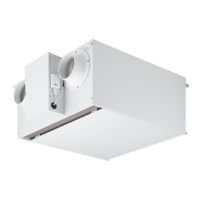
ERV indoor units are factory assembled and provided with an
internally mounted control circuit board, exhaust fan, supply fan,
cross-flow air to air heat exchanger, washable outdoor air and return
air filters, and bypass damper. Each unit is designed to operate
using 208-230/60/1 power with voltage variances of ±10%. ERV
operation range is 14°F - 113°F outdoor temperature.
Casing
The metal casing is designed to mount concealed above a finished
ceiling. Supply fan discharge and exhaust fan inlet (return air)
are front horizontal. Supply fan inlet (outdoor air) and exhaust fan
discharge are rear horizontal. Cold metal surfaces are externally
insulated. The case is provided with hanger brackets designed
to support the unit weight on for corners. Hanger brackets have
pre-punched holes designed to accept field supplied, all-thread rod
hangers.
Fan Assemblies
ERV units have two fans; one fan for supply air and one fan for
exhaust air. Both fans are direct driven. Fan motors are brushless,
digitally-controlled (BLDC) design with permanently sealed
bearings. The fan/motor assemblies are mounted in vibration
attenuated rubber grommets. The fan speeds are controlled using a
microprocessor-based direct digital control algorithm that provides
three fan speeds. Fan speeds are super high, high, and low. Each
fan speed can be adjusted from the factory setting using external
static pressure (ESP) control settings to change fan speeds to
compensate for airflow resistance caused by field installed ductwork.
Cross flow Air-to-air Heat Exchanger
Cross flow air-to-air heat exchanger is constructed of non-
flammable, specially processed paper that allows transfe
r of heat
and humidity. The air-to-air heat exchanger recovers energy from
indoor air as it is exhausted outdoors. The recovered energy is
transferred to the in-coming outdoor air without mixing airstreams.
A hinged access panel allows removal of air-to-air heat exchanger
for vacuum or brush cleaning. Since both heat and humidity are
transferred, condensate drain is not required.
Air Filter
Two washable mesh filters are provided at the outdoor air and return
air inlets of the air-to-air heat exchanger.
Microprocessor Controls
The ERV is provided with an integrated microprocessor-based
controller. All unit operation parameters, excluding the unit operating
schedule, are stored in non-volatile memory, resident on the ERV
microprocessor. Operating schedules are stored in the wall
controller or central controller. ERV units can be operated
independently with a wall controller or interlocked to a Multi V
system. When interlocking to a Multi V system, the field supplied
communication cable between the ERV and outdoor unit is to be
a minimum of 18 AWG, 2-conductor, stranded, and shielded cable
(RS485), terminated via screw terminals on the control board. The
microprocessor control provides the following functions:
• Auto restart following power restoration
• External static pressure (ESP) control of fans
• ERV mode allowing air to pass thru air-to-air heat exchanger
• Bypass mode allowing exhaust air to bypass air-to-air heat
exchanger
The control board is also provided with terminals for connection of
a
field supplied CO2 sensor. DIP switch settings on the control board
allow the ERV to operate independently or as a slave to a Multi V
indoor unit.
Due to our policy of continuous product innovation, some specications may change without notication.
©LG Electronics U.S.A., Inc., Englewood Cliffs, NJ. All rights reserved. “LG” is a registered trademark of LG Corp.
4
Energy Recovery Ventilator Engineering Manual
 Loading...