40 41
39
3. Status Mode Of Wrong Connection
1.Black and White Housing
2.Black Housing
3.White Housing
4.Black and White Housing
5.Black and White Housing
Off
Off
Normal
Heater 2
Off
Off
Off
Normal
Heater 1
Off
Power Off
Power Off
Power On
Power On
Power Off
Wire
ྙ
,
ྚ
CROSS
Wire
ྙ
,
ྚ
CROSS
Wire
ྙ
,
ྚ
CROSS
Housing CROSS
Housing and Wire
ྙ
,
ྚ
CROSS
Items
Case
Heater1
Operation(black)
Heater2
operation(White)
PCB condition
of operation
OffOff
Power Off
Wire
1. Black and white housing
ྙ
,
ྚ
CROSS
Items
Case
Heater 1
Operation (black)
Heater 2
operation (White)
PCB condition
Of operation
CAUTION! Improper connection of the heater can damage the heater or the main board.
H
CAUTION
Connector Housing
Black
Check the matching color between
harness wire and tap relay.
(Black housing – black tap relay)
Color
< Table 2 > : Connection of Tap Relay with PCB ASSEMBLY (Gas)
< Table1 > : Incorrect connection of the tap relay and connector housing (Electric)
< Table2 > : Incorrect connection of the tap relay and connector housing (Gas)
Harness
Remark
PCB
Tap Relay 1
1
2
Blue Wire
Black Wire
Connector Housing
Test 2
{G{GTTTGtGGw Gv
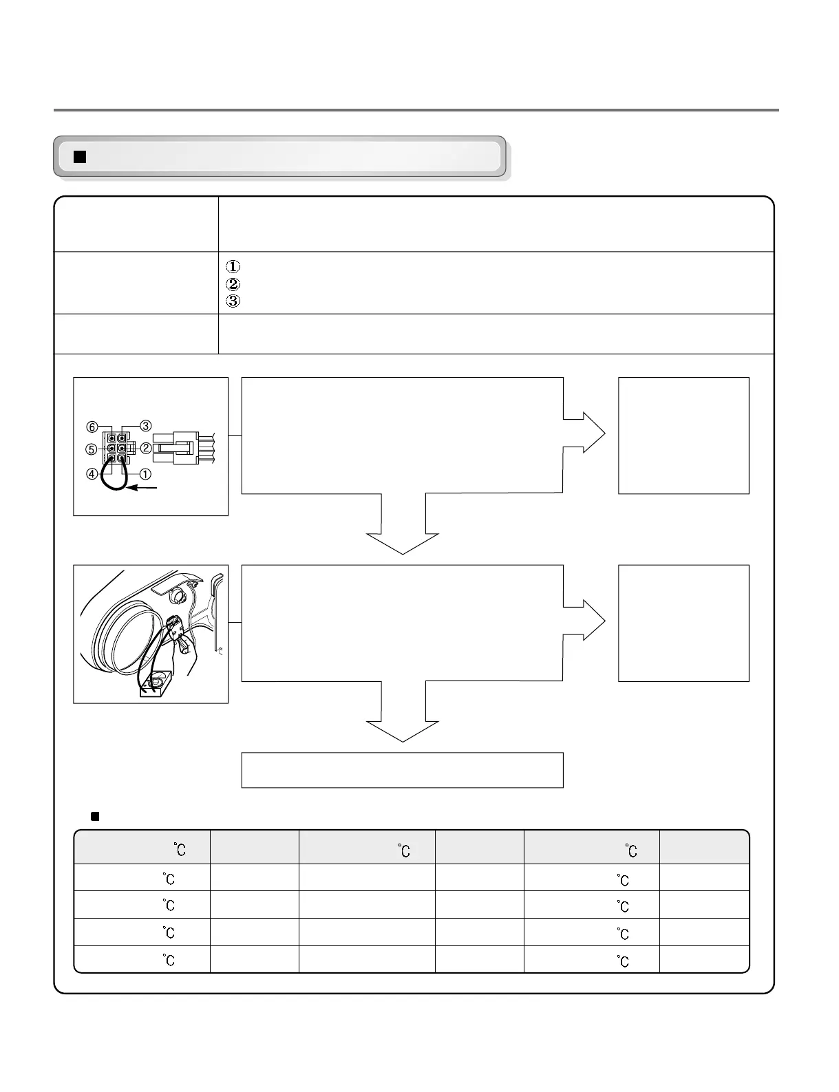
Before measuring resistance, be sure to turn the power off and discharge voltage.
(When discharging, contact the metal plug of power cord with the ground.)
During diagnostic test, tE1 and tE2, an error occurs.
During operation, the heater does not turn off.
Difference between actual and sensed temperature is significant.
After turning power off, measure the resistance.
Short with metal between the NA6 connector’s
Pin ① (Yellow Wire) and Pin ④ (Blue Wire) to
Controller.
• Check if control
and the 6-pin
connector are
properly
connected.
• Replace
controller
• Replace
thermistor.
Check if resistance is in the range of Table 1
when measuring resistance between
terminals after separating harness
from thermistor assembly connector.
Check harness-linking connector.
NO
NO
YES
YES
Table 1. Resistance for Thermistor Temperature.
Air TEMP.
[°F(
)]
50°F (10
)
60°F (16
)
80°F (21
)
70°F (27
)
Air TEMP.
[°F(
)]
90°F (32°C)
100°F (38°C)
110°F (43°C)
120°F (49°C)
RES.
[K
Ω]
18.0
14.2
11.7
9.3
RES.
[K
Ω]
7.7
6.2
5.2
4.3
RES. [KΩ]
2.9
3.0
2.5
2.2
Air TEMP.
[°F(
)]
130°F (54
)
140°F (60
)
150°F (66
)
160°F (71
)
Caution
Trouble Symptom
Measurement Condition
Metal or Wire
Take 6-pin Connector from
the Controller.
 Loading...