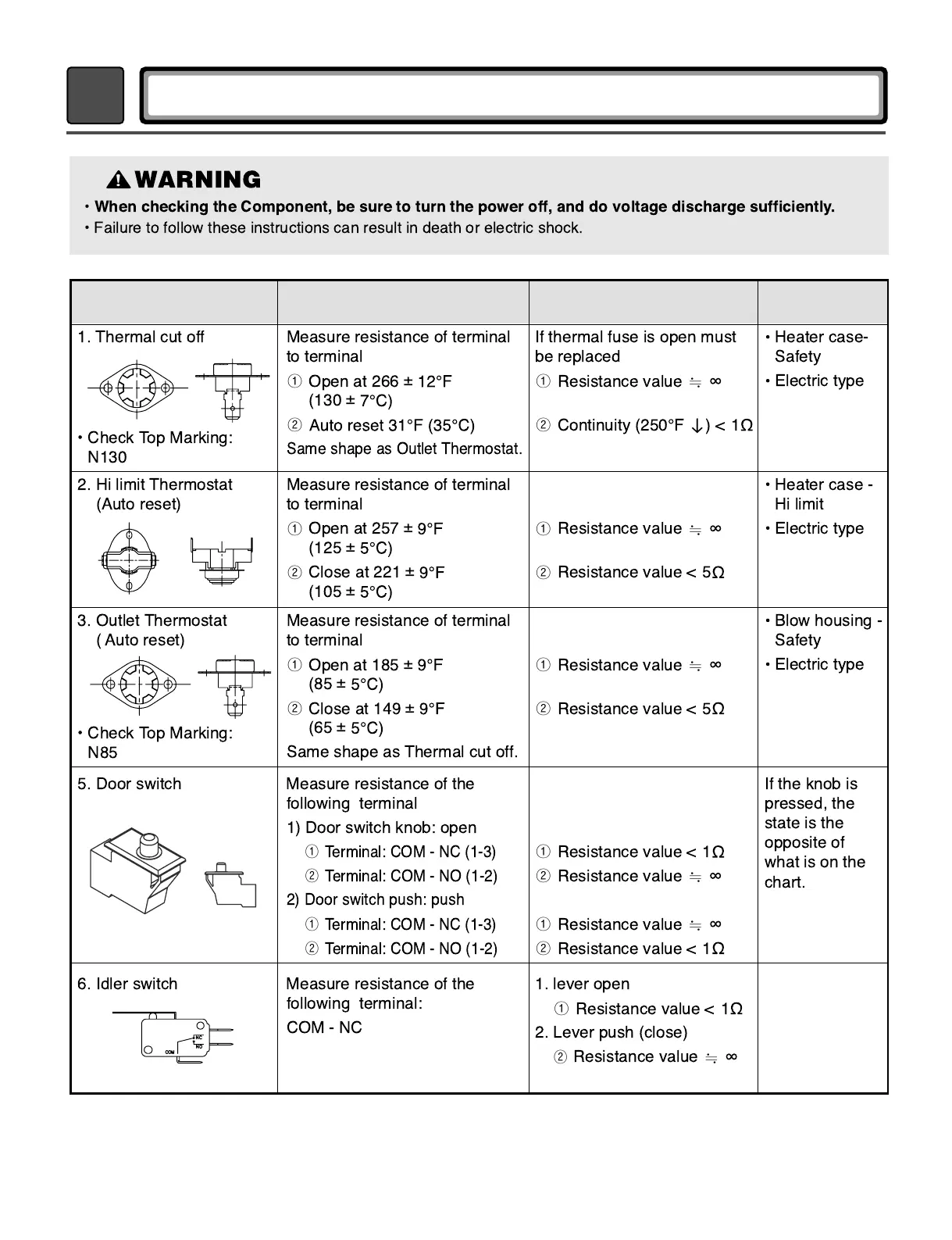
Component Test Procedure Check result Remark
1. Thermal cut off
¥ Check Top Marking:
N130
Measure resistance of terminal
to terminal
ῡ
Open at 266
±
(130
±
ῢ
Same shape as Outlet Thermostat.
If thermal fuse is open must
be replaced
ῡ
Resistance value
ᴾ
ῢ
Continuity (250¡F
ગ
)<1
Heater case-
Safety
Electric type
2. Hi limit Thermostat
(Auto reset)
Measure resistance of terminal
to terminal
ῡ
Open at 257
±
(125
±
ῢ
Close at 221
±
(105
±
ῡ
Resistance value
ᴾ
ῢ
Resistance value < 5
Heater case -
Hi limit
Electric type
3. Outlet Thermostat
( Auto reset)
¥ Check Top Marking:
N85
Measure resistance of terminal
to terminal
ῡ
Open at 185
±
(85
±
ῢ
Close at 149
±
(65
±
Same shape as Thermal cut off.
ῡ
Resistance value
ᴾ
ῢ
Resistance value < 5
Blow housing -
Safety
Electric type
6. Idler switch Measure resistance of the
following terminal:
COM-NC
1. lever open
ῡ
Resistance value < 1
2. Lever push (close)
ῢ
Resistance value
ᴾ
5. Door switch Measure resistance of the
following terminal
1) Door switch knob: open
ῡ
Terminal: COM - NC (1-3)
ῢ
Terminal: COM - NO (1-2)
2) Door switch push: push
ῡ
Terminal: COM - NC (1-3)
ῢ
Terminal: COM - NO (1-2)
ῡ
Resistance value < 1
ῢ
Resistance value
ᴾ
ῡ
Resistance value
ᴾ
ῢ
Resistance value < 1
If the knob is
pressed, the
state is the
opposite of
what is on the
chart.
WARNING
¥ When checking the Component, be sure to turn the power off, and do voltage discharge sufficiently.
¥
Failure to follow these instructions can result in death or electric shock.
 Loading...