1. Explanation for PWB circuit
1-1. Power circuit
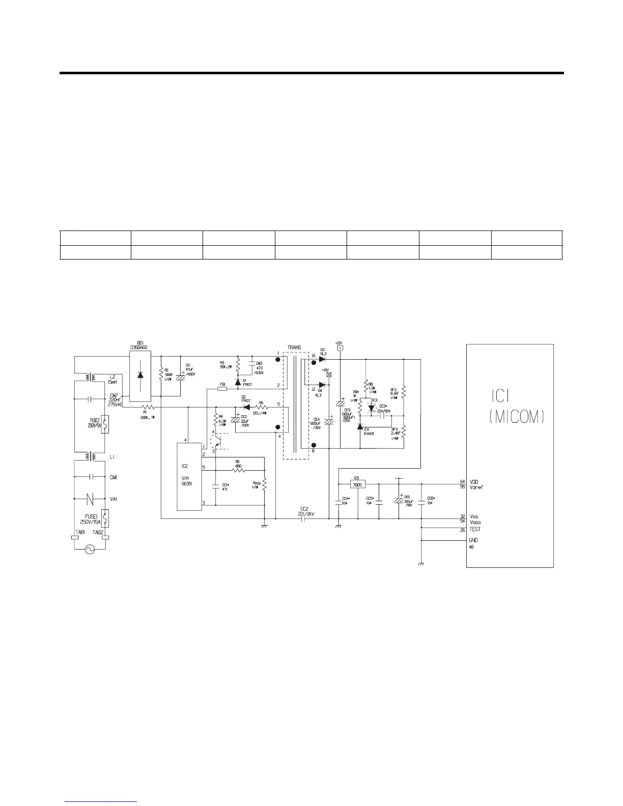
The power circuit includes a Switched Mode Power Supply (SMPS). It consists of a rectifier (BD1 and CE1) converting AC
to DC, a switch (IC2) switching the DC voltage, a transformer, and a feedback circuit (IC3 and IC4).
Caution : Since high voltage (310 Vdc) is maintained at the power terminal, wait at least 3 minutes after unplugging the
appliance to check the voltages to allow the current to dissipate.
Voltage of every part is as follows:
(1) GR-P227/L227
EXPLATION FOR MICOM CIRCUIT
- 27 -
Part VA1 CE1 CE2 CE3 CE4 CE5
Voltage 230 Vac inspection Vdc 13~16 Vdc 12 Vdc 15.5 Vdc 5 Vdc
 Loading...