Do you have a question about the LG LA120CPI and is the answer not in the manual?
Precautions and warnings specific to the installation process of the air conditioner.
Precautions and warnings related to operating the air conditioner safely.
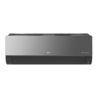
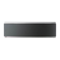
Explanation of symbols used and dimensions of the indoor unit for installation planning.
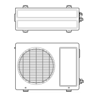
Detailed dimensions of the outdoor unit, critical for placement and installation.
List of necessary parts and tools required for the proper installation of the unit.
Diagrams and clearances required for indoor and outdoor unit placement.
Details on R-410A refrigerant, its properties, and handling precautions.
Criteria for choosing optimal indoor and outdoor unit locations for performance and noise.
Specifications for pipe length, elevation, and refrigerant addition.
Steps for preparing the unit, including front panel and drain hose.
Detailed instructions on securely mounting the indoor unit to the wall.
Steps for cutting, removing burrs, and performing flaring on pipes.
Guidance on connecting indoor unit piping and drain hose, including insulation.
Steps for connecting piping to the outdoor unit service valves.
Wiring schematics and procedures for connecting indoor and outdoor unit electrical cables.
Detailed steps for connecting cables and wiring to terminals.
Procedures to verify proper water drainage from the evaporator and drain hose.
Methods for routing and securing pipes and drain hoses externally.
Steps to remove air and moisture from the refrigerant system using a vacuum pump.
Procedures for vacuum pump evacuation and final valve operations.
Procedures for checking connections, operating the unit, and evaluating performance.
Steps to collect all refrigerant into the outdoor unit for service or relocation.
Overview of various functions and operational modes of the indoor unit.
Explanation of automatic operation modes for cooling, heating, and dehumidification.
Detailed guide to the remote control buttons and their functions.
Step-by-step instructions for disassembling the indoor unit components.
Electrical schematic diagram for the indoor unit's circuitry.
Wiring diagram illustrating connections within the indoor unit.
Diagrams illustrating the refrigerant flow in cooling-only and cooling/heating models.
Detailed steps for evacuating the refrigerant system.
Steps for charging the system with refrigerant after evacuation.
Troubleshooting steps for electronic components and PCB checks.
Troubleshooting steps when the product does not operate with the remote controller.
Diagram showing the assembly of indoor unit components with part numbers.
List of replacement parts for the indoor unit with part numbers and models.
List of replacement parts for the outdoor unit with part numbers and models.
| Cooling Capacity | 12000 BTU/h |
|---|---|
| Refrigerant | R410A |
| Power Supply | 220-240V, 50Hz |
| Type | Split Air Conditioner |
| Noise Level (Indoor) | 42 dB |
| Operating Temperature (Cooling) | 18°C to 43°C |