Do you have a question about the LG LG-500 and is the answer not in the manual?
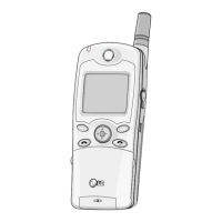
Identifies the product as LG-500.
Lists GSM standards, frequency ranges, and application standards.
Lists the main chipset components of the GSM solution.
Details language, SIM toolkit, phone book, schedule, games, clock, calculator, and WAP.
Covers form factor, battery, size, weight, PCB, talk/standby times, RX sensitivity, TX output, display, keypad, and connectors.
Details memory specifications and supported speech coding standards.
Covers vibrator, melody, microphone, speaker, adapter, and accessories.
Details display, keypad, normal features, call management, voice dialling, and network settings.
Covers DTMF, audio levels, ring tones, cell broadcast, and voice recording.
Lists call forwarding and barring options.
Details SIM card interaction, messaging protocols, and voice mail.
Includes multi-band support, test facilities, and text input methods.
Covers WAP browser, world time, calculator, and unit conversion.
Details PC synchronization and available game features.
Illustrates and labels the physical arrangement of keys on the phone.
Describes the functionality of each key on the keypad.
Provides initial steps for disassembling the phone, starting with the battery cover.
Details the process of removing the battery cover and battery.
Continues the process of separating the upper and lower cases.
Describes how to remove the speaker and vibrator from the upper case.
Details removal of battery spring and SIM card cover.
Explains how to remove the PCB and the flip cover from the lower case.
Details removal of microphone, receiver, and hinge components.
Describes the process of removing the main PCB and LCD module, and the antenna.
Provides instructions for reassembling the PCB and the upper/lower cases.
Introduces the data kit and its purpose for software upgrading.
Lists the necessary equipment for software download.
Outlines the general purpose and download environment for software updates.
Details the initial steps of executing the download monitor program and selecting the serial port.
Describes connecting the phone and confirming successful detection in the monitor program.
Explains selecting the flash option and choosing the target software for download.
Details the final steps of the downloading procedure and confirmation.
Lists the necessary test equipment for phone diagnostics.
Shows a diagram of how the test equipment should be connected.
Introduces troubleshooting procedures for common phone issues.
Provides a flowchart for diagnosing power-on problems.
Offers a flowchart for diagnosing microphone issues.
Provides a flowchart for diagnosing receiver problems.
Presents a flowchart for troubleshooting melody playback issues.
Offers a flowchart for diagnosing LCD display problems.
Provides a flowchart for diagnosing battery charging issues.
Presents a flowchart for diagnosing vibrator malfunctions.
Offers a flowchart for diagnosing backlight failures.
Provides a flowchart for diagnosing TX power issues.
Offers a flowchart for diagnosing Rx sensitivity in E GSM.
Provides a flowchart for diagnosing Rx sensitivity in DCS.
Shows the component layout on the first copper layer of the PCB.
Displays the component layout on the eighth copper layer of the PCB.
Illustrates the block diagram of the baseband processing unit.
Presents the block diagram of the radio frequency section.
Shows the schematic connections related to the baseband chipset.
Details the schematics for memory components.
Displays the schematic for the audio circuitry.
Shows the schematic for the Man-Machine Interface components.
Presents the schematic for the Pascal RF component.
Details the schematic for the Hitachi Power Amplifier.
Provides a detailed schematic for the baseband section.
Details the baseband connections to the RF section.
Shows the detailed schematic for the Pascal RF component.
Presents the schematic for the Hitachi Power Amplifier.
A visual representation of the phone's components and their assembly.
Lists part numbers, descriptions, specifications, and remarks for replacement parts.
| 2G bands | GSM 900 / 1800 / 1900 |
|---|---|
| GPRS | Class 10 |
| SIM | Mini-SIM |
| Secondary | No |
| 3.5mm jack | No |
| WLAN | No |
| GPS | No |
| Browser | WAP 2.0/xHTML |
| Java | Yes, MIDP 2.0 |
| Talk time | Up to 3 h |
| Card slot | No |
| Alert types | Vibration; Downloadable polyphonic ringtones |
| Messaging | SMS, EMS, MMS |
| Games | Yes |
| Battery | Removable Li-Ion battery |
| Colors | Black |