7-7
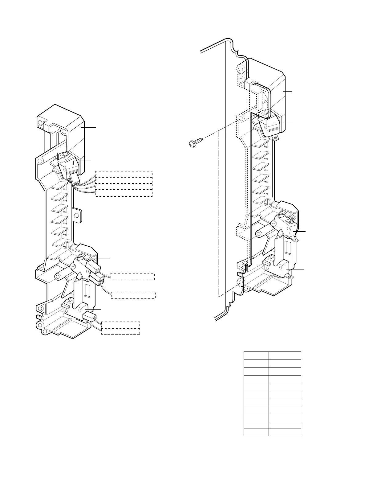
C REMOVING THE DOOR INTERLOCK
SWITCHES (Figures 9, 10)
(1) Disconnect the wire leads from the interlock
switches.
(2) Remove two screws securing the Latch Board.
(3) Make necessary replacements and check
microwave energy leakage according to
“ADJUSTMENT PROCEDURES ” on page 7-12.
Latch Board
Primary Interlock Switch
RD(from P.C.B)
RD(from Fan Motor)
BK(from Cooktop lamp)
WH(from H.V.T)
PK(from P.C.B)
BL(from P.C.B)
RD(from P.C.B)
BK
(from MGT THERMOSTAT)
Monitor Interlock Switch
Secondary Interlock Switch
Latch Board
Primary
Interlock Switch
Interlock
Monitor Switch
Secondary
Interlock Switch
Figure 9
Figure 10
WIRE COLOR
SYMBOL COLOR
WH WHITE
BK BLACK
BR BROWN
RD RED
YL YELLOW
PK PINK
BL BLUE
GY GREY
GN GREEN
N.P.
Not Provided
 Loading...