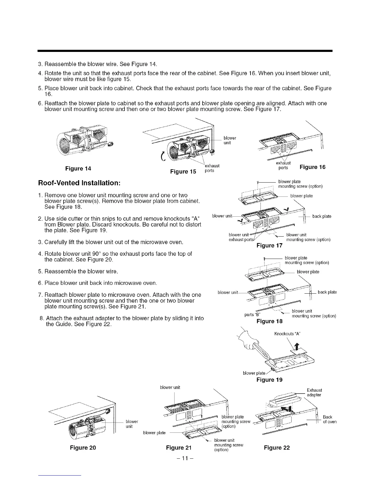
3.Reassembletheblowerwire.SeeFigure14.
4.Rotatetheunitsothattheexhaustportsfacetherearofthecabinet.SeeFigure16.Whenyouinsertblowerunit,
blowerwiremustbelikefigure15.
5.Placeblowerunitbackintocabinet.Checkthattheexhaustportsfacetowardstherearofthecabinet.SeeFigure
16.
6.Reattachtheblowerplatetocabinetsotheexhaustportsandblowerplateopeningarealigned.Attachwithone
blowerunitmountingscrewandthenoneortwoblowerplatemountingscrew.SeeFigure17.
Figure 14
Roof-Vented Installation:
exhaust
Figure 15 ports
1. Remove one blower unit mounting screw and one or two
blower plate screw(s). Remove the blower plate from cabinet.
See Figure 18.
2. Use side cutter or thin snips to cut and remove knockouts "A"
from Blower plate. Discard knockouts. Be careful not to distort
the plate. See Figure 19.
3. Carefully lift the blower unit out of the microwave oven.
4. Rotate blower unit 90° so the exhaust ports face the top of
the cabinet. See Figure 20.
5. Reassemble the blower wire.
6. Place blower unit back into microwave oven.
7. Reattach blower plate to microwave oven. Attach with the one
blower unit mounting screw and then the one or two blower
plate mounting screw(s). See Figure 21.
8. Attach the exhaust adapter to the blower plate by sliding it into
the Guide. See Figure 22.
blower
unit
ports Figure 16
blower plate
.... mounting screw (option)
_ blower plate
blower unit back plate
blower unit_ _-'-_blower unit
exhaust portsY mounting screw (option)
Figure 17
blower plate
i.......... i mounting screw (option)
_ blower plate
"a
blowerunit__ backplate
- __,=r,,,_it'-- _'_ blower unit
parts "B" mounting screw (option)
Figure 18
"2_ Knockouts"A"
\
Figure 20
blower
unit
blower plate/
Figure 19
blower unit
__wer plate
nll; gscrew_
blower plate _'
blower unit
mounting screw
Figure 21 (option) Figure 22
-11 -
Exhaust
adapter
Back
- ofoven
 Loading...