Do you have a question about the LG LT1430CNR and is the answer not in the manual?
Essential safety measures to follow before and after servicing the air conditioner unit.
Detailed steps for performing an insulation resistance test to ensure user safety.
Comprehensive technical specifications including performance, electrical ratings, features, and dimensions.
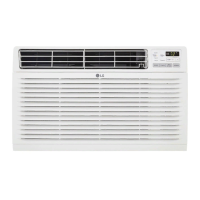
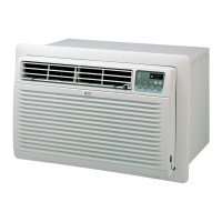
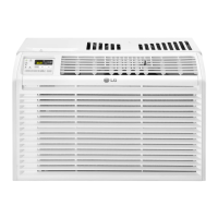
Key features of the cooling-only air conditioner, such as powerful cooling and compact design.
Overview of control locations on the unit and remote, explaining their functions.
Detailed operation of controls specific to the cooling-only model, including fan speed, timer, and mode.
Procedures for removing the front grille and the main cabinet of the unit.
Steps to safely remove and discharge the control box and its components.
Instructions for removing air handling components like the orifice, turbo fan, and main fan.
Steps for removing the shroud after disassembling the fan.
Procedure for removing the motor, including disconnecting wires and fan components.
Steps to safely discharge refrigerant and remove the compressor.
Instructions for removing the capacitor after opening the control box.
Steps for removing the power cord, including disconnecting receptacles and clip cord.
Procedure for removing the thermistor from the control box.
Steps for removing condenser, evaporator, and capillary tube, involving refrigerant handling.
Key requirements for successful installation, including wall sleeve compatibility and electrical service.
Step-by-step guides for installing the air conditioner into a wall sleeve (Procedures A, B, C).
Provides outside dimensions and a diagram of the refrigeration piping system.
Brief description of the refrigerant flow and components in the cooling cycle.
Flowchart for diagnosing ineffective cooling, covering causes like dirty coils, fan malfunction, and gas leakage.
Flowchart for diagnosing units that fail to start, addressing power, wiring, and component issues.
Electrical circuit diagram showing components and connections for the air conditioner.
Visual representation of all components with associated part numbers for identification and ordering.
| Type | wall |
|---|---|
| Operating Area Size | 750 square feet |
| Cooling Capacity | 14000 british thermal units |
| Cooling Settings | 3 |
| Heater | no |
| Fan Speeds | 3 |
| Fan Airflow Rate | 4 cubic feet per minute |
| Remote Control | yes |
| Timer | yes |
| Sleeping Mode | no |
| Energy Efficiency | 9.3 |