Do you have a question about the LG LUU247HV and is the answer not in the manual?
Specifies the capacity range covered by the heat pump systems.
Document is property of LG Electronics U.S.A., Inc. and is disclosed in confidence.
Overview of LG Electronics' five business units and their product lines.
Highlights cost efficiency, quiet operation, and flexibility of DFS systems.
Details advanced controls for dehumidification, temperature, and rapid parameter adaptation.
Describes LG's commitment to technical support and installer training programs.
Explains the meaning of DANGER, WARNING, CAUTION, and NOTE symbols used in the manual.
References discussion on the aesthetic design of the units on the following page.
Describes the system's design for flexibility, style, and clean appearance.
Highlights quieter operation and reduced energy consumption of inverter compressors.
Lists various residential and commercial environments where the systems are suitable.
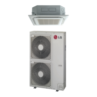
Provides an overview of the key features and advantages of the four-way ceiling cassette systems.
Explains the coding system used for identifying unit models and their components.
Presents general technical specifications and pairing information for the system.
Details the system's features, including inverter technology and design flexibility.
Discusses the quiet operation of both indoor and outdoor units.
Explains precise temperature control via inverter technology and variable refrigerant flow.
Highlights how inverter technology maximizes compressor efficiency and reduces utility costs.
Describes how the system simplifies mechanical and control system design and installation.
Details the specified operating temperature ranges for cooling and heating modes.
Focuses on the flush-mounted, clean look provided by the indoor unit grille.
Explains the design of outdoor unit coils and GoldFin™ coating for efficient heat transfer.
Lists additional features such as auto restart, auto changeover, and internal condensate pump.
Explains the meaning of each character in the unit model number for identification.
Shows available outdoor and indoor unit pairings with their respective controllers.
Provides detailed cooling, heating, and operational specifications for the system.
Continues the detailed technical specifications for cooling, heating, and operational parameters.
Lists electrical data including voltage, MCA, MOP, and motor ratings for outdoor units.
Provides detailed dimensional drawings and specifications for LUU097HV and LUU127HV outdoor units.
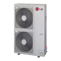
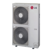
Provides detailed dimensional drawings and specifications for LUU187HV and LUU247HV outdoor units.
Provides detailed dimensional drawings and specifications for LUU367HV and LUU427HV outdoor units.
Provides detailed dimensional drawings and specifications for LCN097HV4 and LCN127HV4 indoor units.
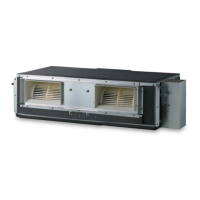
Provides detailed dimensional drawings and specifications for LCN187HV and LCN247HV indoor units.
Provides detailed dimensional drawings and specifications for LCN367HV and LCN427HV indoor units.
Presents sound pressure levels for outdoor units in cooling and heating modes.
Presents sound pressure levels for indoor units in various operating modes and speeds.
Illustrates air velocity and temperature distribution for LCN097HV4 in cooling and heating.
Illustrates air velocity and temperature distribution for LCN127HV4 in cooling and heating.
Illustrates air velocity and temperature distribution for LCN187HV in cooling and heating.
Illustrates air velocity and temperature distribution for LCN247HV in cooling and heating.
Illustrates air velocity and temperature distribution for LCN367HV in cooling and heating.
Illustrates air velocity and temperature distribution for LCN427HV in cooling and heating.
Diagram illustrating the refrigerant flow for LUU097HV and LUU127HV outdoor units.
Diagram illustrating the refrigerant flow for LCN097HV4 and LCN127HV4 indoor units.
Diagram illustrating the refrigerant flow for LUU187, 247, 367, 427HV outdoor units.
Diagram illustrating the refrigerant flow for LCN187, 247, 367, 427HV indoor units.
Wiring diagram for LUU097HV and LUU127HV outdoor units, showing connections and components.
Wiring diagram for LUU187HV and LUU247HV outdoor units, detailing electrical connections.
Wiring diagram for LUU367HV and LUU427HV outdoor units, illustrating component connections.
Wiring diagram for LCN097, 127HV4 indoor units, showing terminal block and control connections.
Wiring diagram for LCN187, 247, 367, 427HV indoor units, detailing connections for various components.
Lists functions, controls, and options available for indoor units and their accessories.
Details the LGMV software for viewing real-time data and troubleshooting systems.
Provides detailed cooling capacity tables for various operating conditions.
Presents cooling capacity tables for LC097HV4 system under different temperatures.
Presents cooling capacity tables for LC127HV4 system under various indoor and outdoor conditions.
Presents cooling capacity tables for LC187HV system under various temperature conditions.
Presents cooling capacity tables for LC247HV system under varying temperature conditions.
Presents cooling capacity tables for LC367HV system under different operational conditions.
Presents cooling capacity tables for LC427HV system across a range of temperatures.
Presents heating capacity tables for LC097HV4 system under various conditions.
Presents heating capacity tables for LC187HV and LC247HV systems under various conditions.
Presents heating capacity tables for LC367HV and LC427HV systems under various conditions.
Details the process for selecting appropriate equipment based on load calculations and system requirements.
Provides guidance on ventilation methods and considerations for building design.
Offers recommendations and guidelines for optimal placement of system components.
Explains how to adjust capacity based on liquid line length and elevation differences.
Details capacity correction factors based on the length of the refrigerant piping.
Describes how to adjust heating capacity considering frost accumulation on outdoor units.
Guidance on comparing corrected capacities against design loads for proper system sizing.
Presents formulas for checking system capacity and calculating corrections.
Offers final recommendations and considerations for system design and selection.
Explains using natural ventilation methods like windows and louvers for air exchange.
Details using fan-assisted systems to draw unconditioned outdoor air into occupied spaces.
Describes channeling untreated outdoor air via ductwork to indoor units or return air ducts.
Explains delivering air from a separate system directly to indoor units or return air ducts.
Details providing conditioned ventilation air directly to spaces via separate registers.
Provides guidelines for selecting the best location for installing indoor units.
Addresses installation challenges and countermeasures for high or dropped ceilings.
Covers placement in areas exposed to unconditioned air or high humidity levels.
Details the requirements and procedures for installing the condensate drain system.
Provides guidelines for selecting the best location for installing outdoor units.
Offers advice on installation strategies to mitigate issues related to snow and ice buildup.
Covers wind restraints, lightning protection, and safety zone specifications for outdoor units.
Details secure mounting methods and bracket installation for outdoor units.
Explains the procedure and specifications for bolting outdoor units to mounting platforms.
Details the recommended materials and finishing for concrete foundations.
Specifies minimum clearances for service access and airflow for 9,000 to 24,000 Btu/h outdoor units.
Specifies minimum clearances for service access and airflow for 36,000 to 42,000 Btu/h outdoor units.
Illustrates clearance requirements when obstacles are present around the outdoor unit.
Illustrates clearance requirements for different obstacle positions relative to the outdoor unit.
Provides guidelines for designing the refrigerant piping system.
Details the selection criteria and specifications for field-supplied copper tubing.
Offers best practices for laying out the refrigerant piping system.
Summarizes key design guidelines and limitations for refrigerant piping systems.
Lists pipe length and elevation limits for connecting outdoor and indoor units.
Illustrates typical refrigerant piping system layouts for different model series.
Provides radii of coiled expansion loops and developed lengths for offsets.
Details linear thermal expansion of copper tubing at various temperatures.
Covers elbows, isolation ball valves, obstacles, and in-line components for piping.
Provides guidance on routing refrigerant pipes around obstacles like I-beams.
Specifies permitted and prohibited in-line refrigeration components for the system.
Covers best practices for laying out the refrigerant piping system, including supports.
Emphasizes the prohibition of substituting pipe sizes to avoid system malfunction.
Details the use of inserts and pipe supports to prevent sagging and ensure system integrity.
Provides guidelines for installing pipe supports and spacing to avoid sagging.
Covers pipe sleeves at penetrations and underground refrigerant piping requirements.
Details requirements for pipe sleeves at wall, floor, and roof penetrations.
Provides guidelines for routing refrigerant pipes underground with protective sleeves.
Explains the process for connecting refrigerant pipes to outdoor units, including torque specifications.
Details the steps for removing covers and connecting refrigerant pipes to outdoor units.
Covers brazing practices and flare connection procedures for refrigerant piping.
Provides best practices for brazing refrigerant piping, emphasizing cleanliness and nitrogen purging.
Details flare connection procedures, including tightening torque and insulation.
Covers refrigerant piping insulation requirements and system charging procedures.
Specifies insulation thickness and protection methods for refrigerant piping.
Explains how to adjust refrigerant charge based on line set length and provides charging capacity.
Details requirements for condensate drain piping construction, slope, and insulation.
Describes factory-installed drain pumps and options for draining condensation.
Details the process for connecting power and communication cables to outdoor units.
Explains how to connect power and communication cables to indoor unit control boxes.
Details the procedure for using a conduit to protect wiring and cable connections.
Presents a schematic of the detailed power and communications wiring between indoor and outdoor units.
References the section detailing mechanical specifications of the ceiling cassette system.
Provides an overview of the LG single zone four-way ceiling cassette system.
Covers sound levels, casing, and operating ranges for outdoor units.
Covers sound ratings, casing, and operating ranges for indoor units.
Details the operating temperature ranges for cooling and heating for different system capacities.
Describes the refrigerant system, components, and pressure testing.
Explains the specifications and features of the inverter-driven twin rotary compressor.
Details the construction and materials of the outdoor and indoor unit coils.
Describes the fans and motors used in outdoor and indoor units, including BLDC technology.
Describes the removable, washable air filter accessible from the bottom of the indoor unit.
Covers the electrical system design, power requirements, and voltage variances.
Explains the factory-wired electrical components and microprocessor controls for system operation.
Details the condensate lift/pump capabilities and safety switch functionality.
Provides a comprehensive list of acronyms and their definitions used throughout the manual.
| HSPF | 9.5 |
|---|---|
| Phase | 1 |
| Refrigerant | R410A |
| Cooling Capacity (BTU/h) | 24000 |
| Heating Capacity (BTU/h) | 27000 |
| Voltage (V) | 208-230 |
| Power Supply (V/Ph/Hz) | 208-230 / 1 / 60 |