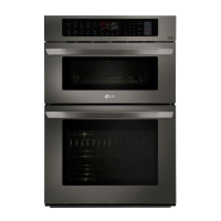
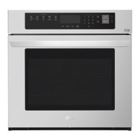
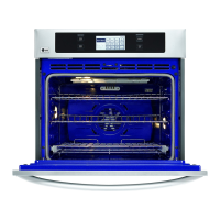
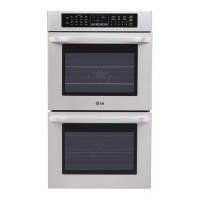
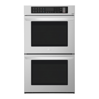
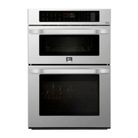
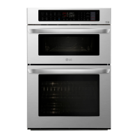
LWC3063_
Combi Wall Oven
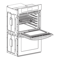
DIMENSIONS / CLEARANCES / WEIGHT
Product Dimensions (in) (W x H x D) 29 3/4" x 43 13/16" x 24 1/2"
Cut-out (W x H x D) 28 1/2" x 43 8/19" x 23 1/2
Overall Depth (in) - including handle 26 7/8"
Actual Depth with Door Open (Upper) (in): 37.1"
Actual Depth with Door Open (Lower) (in): 45.7”
Oven Interior Dimensions (Upper) (in) (W x H x D) 20 8/11" x 8 9/25" x 17 5/13"
Oven Interior Dimensions (Lower) (in) (W x H x D) 24 1/2" x 17 5/8" x 18 7/8"
Carton Dimensions (in) (W x H x D) 33" x 30" x 50"
POWER RATINGS
Amp at 240V 32.5A
kW at 240V 7.8kW
Requirements 120 / 240 VAC, 120 / 208 VAC
•
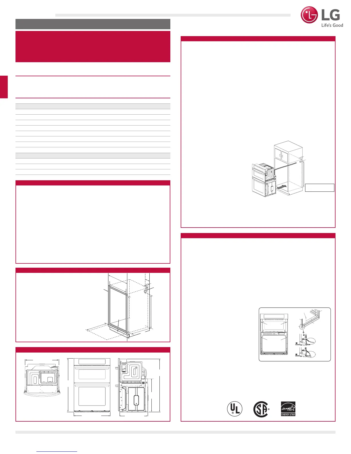
Install the oven into the cabinet as follows:
•
Slide the oven into the opening.
a. Loop (do not tie) a 36” (91 cm) string around the conduit before the oven is slid
into place. Lay the string over the top of the oven and use it to keep the conduit
from falling behind the oven.
b. Lift oven into cabinet cutout using the oven opening as a grip. Carefully push
against the oven front frame. Do not push against outside edges.
c. While sliding the oven back, pull the string so that the conduit lies on the top of
the oven in a natural loop.
d. When you are sure the conduit is out of the way, slide the oven 3/4 way back
into the opening. Remove the string by pulling on one end of the loop.
•
Secure the oven.
a. Using the mounting holes on the
oven side trim as a guide, drill pilot
holes for screws provided. (For
securing the Combi Oven, use a
minimum of 4 screws, one on each
side in both the upper and lower
ovens.)
b. Secure the oven to the cabinet with
screws provided. If the cabinet is
particle board, you must use 3/4”
particle board screws. These may be
purchased at any hardware store.
•
Install the metal bottom trim.
a. Place the metal bottom trim centered over the pre-drilled mounting holes on the
lower base.
b. Using 3 screws provided, secure the bottom trim to the bottom edge of the
cabinet.
•
Reinstall the oven door.
•
The cabinet base platform must be able to support 202 lbs (91.65 kg) for a
Microwave Combination Wall Oven. If the cabinet does not have a solid bottom,
two braces or runners must be installed level with the bottom of the cutout to
support the weight of the oven. Make sure the base is level and the front of the
cabinet is square. If the cabinet base is not level, the oven racks will tend to slide
out when opening the door.
•
If marks, blemishes or the cutout opening are visible above the installed oven, it
may be necessary to add wood shims under the runners and front trim until the
marks or opening are covered.
•
If the cabinet does not have a front frame and the sides are less than 3/4” (1.9
cm) thick, shim both sides equally to establish the cutout width.
•
The junction box must be ush with the rear wall of the cabinet as shown below.
•
Allow at least a 23” clearance for the door depth when it is open.
•
Kitchen cabinets in contact with the oven must be heat resistant up to 194°F
(90°C), and fronts of nearby units up to at least 158°F (70°C).
HOME APPLIANCES
QUICK INSTALL & CLEARANCES
For full installation directions/clearances please refer to
the corresponding User Manual and Installation Guide.
IMPORTANT
•
Be sure the wall oven is installed and grounded properly by a qualied
installer or service technician.
•
This wall oven must be electrically grounded in accordance with local codes or, in
their absence, with the National Electrical Code ANSI/NFPA No.70- latest edition
in United States, or with CSA Standard C22.1-1982 and C22.2 No.01982 (or
latest edition), Canadian Electrical Code, Part1, and all local codes and ordinances.
•
This wall oven must be supplied with the proper voltage and frequency, and
connected to an individual, properly grounded branch circuit, protected by a circuit
breaker or fuse. For the circuit breaker or fuse required by this model, see the
rating plate to nd the wattage consumption and refer to the table below to get
the circuit breaker or fuse amperage.
•
A Microwave Combination Wall Oven can consume up to 7,800 W at 240 VAC. A
50 Amp circuit breaker with wire gauge #8 AWG must be used.
•
Do Not ground to a gas pipe.
•
Do Not have a fuse in the neutral or grounding circuit.
•
A U.L.-listed conduit connector must be provided at the junction box.
•
Prepare the electrical connection as follows:
•
Turn off the circuit breaker or
remove fuses to the oven branch
circuit.
•
With the oven positioned directly
in front of the cabinet opening,
connect the exible conduit to the
electrical junction box as shown
below. Position the conduit in such
a manner that it will lie on top of
the oven in a natural loop when the
oven is installed.
•
If local codes permit connection of
the frame grounding conductor to the neutral(white) wire, follow the instructions
for a 3-wire circuit connection.
•
If used in mobile homes or new construction, or a recreational vehicle, or local
codes do not permit connection of the frame grounding conductor to the
neutral(white) wire, follow the instructions for a 4-wire circuit connection.
INSTALL THE OVEN
INSTALLATION REQUIREMENTS
ELECTRICAL CONNECTIONS
•
Cabinet Width: 30”
(762 mm)
•
Recommended
Minimum
Cutout Location
12”
(304.8 mm)
from Floor:
•
Cutout Depth: 23 1/2” Min.
(596.9 mm)
•
Cutout Width: 28 1/2” Min.
(723.9 mm)
28 5/8” Max.
(727 mm)
•
Cutout Height: 43 7/16” Min.
(1103 mm)
43 1/2” Max.
(1106 mm)
Junction Box
Location
41”
(1041.0 mm)
30”
23”
5”
28 1/2” Min.
28 5/8” Max.
43 7/16” Min.
(1103 mm)
43 1/2” Max.
(1106 mm)
Allow 1”
minimum for
overlap of oven
Allow 1”
minimum for
overlap of oven
23 1/2”
Minimum cutout location from floor 12”
27 3/8” (69.5 cm)
43 13/16”
(111.3cm)
43 3/16”
(109.7 cm)
27 1/6”
(69 cm)
29 3/4” (75.5 cm) 23 3/8” (59.3cm)
Spacer
Junction Box
Location
41” Min
for Microwave Combination Wall Oven
Junction Box must be recessed
and conduit connector must be
used at Junction Box.
5” Min
White
Green
Black
Red
Neutral
Wire nut
Junction Box
White
Green
Black
Red
Neutral
Wire nut
Junction Box
Hinge arm
Bottom
edge of
slot
Indentation
Hinge arm
Hinge lock
Mounting
Hole
Locations
Mounting
Hole
Locations
Trim Screws
Side
Trim
Side Trim
Lower base
Metal Trim:
Correct
position
Metal Trim:
Wrong
position
Metal
bottom
trim
Hinge
lock
Slot
Lock
Unlock
about 5
CUTOUT DIMENSIONS
PRODUCT DIMENSIONS
Junction Box
Location
41”
(1041.0 mm)
30”
23”
5”
28 1/2” Min.
28 5/8” Max.
43 7/16” Min.
(1103 mm)
43 1/2” Max.
(1106 mm)
Allow 1”
minimum for
overlap of oven
Allow 1”
minimum for
overlap of oven
23 1/2”
Minimum cutout location from floor 12”
27 3/8” (69.5 cm)
43 13/16”
(111.3cm)
43 3/16”
(109.7 cm)
27 1/6”
(69 cm)
29 3/4” (75.5 cm) 23 3/8” (59.3cm)
Spacer
Junction Box
Location
41” Min
for Microwave Combination Wall Oven
Junction Box must be recessed
and conduit connector must be
used at Junction Box.
5” Min
White
Green
Black
Red
Neutral
Wire nut
Junction Box
White
Green
Black
Red
Neutral
Wire nut
Junction Box
Hinge arm
Bottom
edge of
slot
Indentation
Hinge arm
Hinge lock
Mounting
Hole
Locations
Mounting
Hole
Locations
Trim Screws
Side
Trim
Side Trim
Lower base
Metal Trim:
Correct
position
Metal Trim:
Wrong
position
Metal
bottom
trim
Hinge
lock
Slot
Lock
Unlock
about 5
Junction Box
Location
41”
(1041.0 mm)
30”
23”
5”
28 1/2” Min.
28 5/8” Max.
43 7/16” Min.
(1103 mm)
43 1/2” Max.
(1106 mm)
Allow 1”
minimum for
overlap of oven
Allow 1”
minimum for
overlap of oven
23 1/2”
Minimum cutout location from floor 12”
27 3/8” (69.5 cm)
43 13/16”
(111.3cm)
43 3/16”
(109.7 cm)
27 1/6”
(69 cm)
29 3/4” (75.5 cm) 23 3/8” (59.3cm)
Spacer
Junction Box
Location
41” Min
for Microwave Combination Wall Oven
Junction Box must be recessed
and conduit connector must be
used at Junction Box.
5” Min
White
Green
Black
Red
Neutral
Wire nut
Junction Box
White
Green
Black
Red
Neutral
Wire nut
Junction Box
Hinge arm
Bottom
edge of
slot
Indentation
Hinge arm
Hinge lock
Mounting
Hole
Locations
Mounting
Hole
Locations
Trim Screws
Side
Trim
Side Trim
Lower base
Metal Trim:
Correct
position
Metal Trim:
Wrong
position
Metal
bottom
trim
Hinge
lock
Slot
Lock
Unlock
about 5
© 2018 LG Electronics USA, Inc. All rights reserved. "LG Life’s Good" is a registered trademark of LG Corp. All other product and brand names are trademarks or registered trademarks of their respective owners. Design, features and specifications are subject to
change without notice. Non-metric weights and measurements are approximate. Some features may require Internet access. Content and services may vary by product and are subject to change without notice. 10/4/18
LG COOKING
 Loading...