2-8
ORDER OF ASSEMBLY FOR MECHANISM DECK
1
2
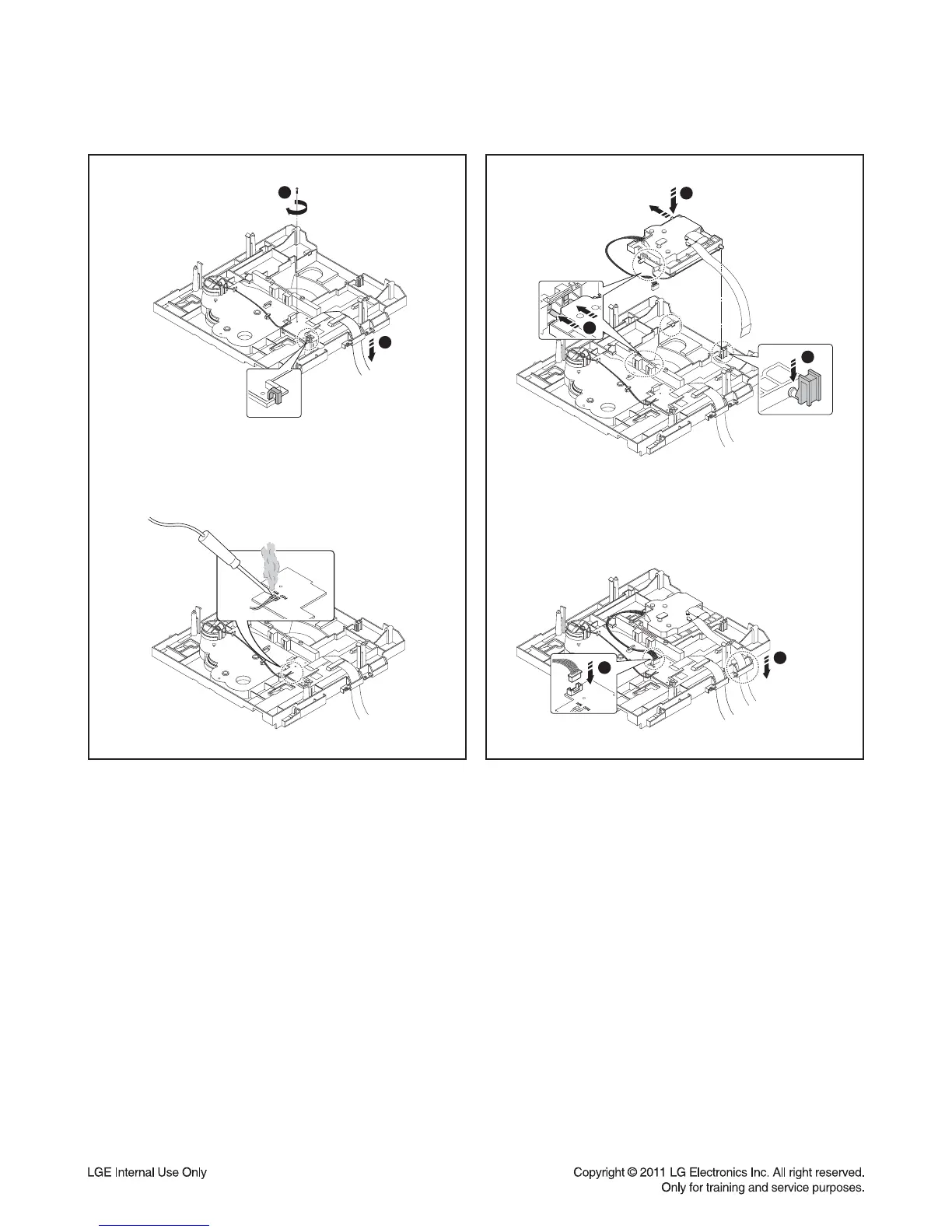
Figure 5
4
5
3
2
1
Figure 6
5) After setting the Main PCB Assy on the Base Main,
tighten the screw.
(Set the part accurately on the hook)
Solder the Motor Jump Wire on the PCB set on the
Base Main.
6) Set the Base Sled Assy on the Base Main.
(When setting the part, assemble with the CAM part of
the Guide UD inserted in two locations of the Boss of
Frame UD)
Align the FFC to the Guide and connect the Harness Cable.