Do you have a question about the LG MCV903 and is the answer not in the manual?
Important notes regarding the safe handling and servicing of the pick-up unit.
Troubleshooting guide for the audio electrical components of the system.
Second part of the MICOM troubleshooting procedure with detailed checks.
Third part of the MICOM troubleshooting procedure, including waveform checks.
Troubleshooting steps for the FLD display part, including voltage and signal checks.
Specific checks for the IC103 S-24CS16A01-J8T1GE component.
Troubleshooting guide for the AUX function, checking various ICs and waveforms.
Troubleshooting steps for the power amplifier section, checking ICs and power supply.
Schematic diagram for the SMPS (Switch Mode Power Supply) section.
Schematic diagram for the SMPS Sub section, detailing power filtering and protection.
Schematic diagram for the Tape Deck mechanism, including component values and options.
Schematic diagram for the Main Amplifier section, showing power stages and protection circuits.
Schematic diagram for the Woofer Amplifier section, detailing its connections and operation.
Schematic diagram for the Front PCB, showing controls, LEDs, and connections to other boards.
Troubleshooting guide for the CD electrical components and mechanisms.
Troubleshooting steps for USB device detection and file playback issues.
Waveform examples for Flash/SDRAM signals for diagnostics.
| Brand | LG |
|---|---|
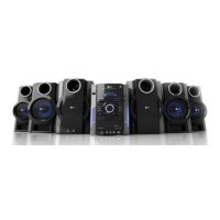
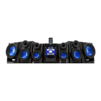
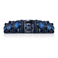
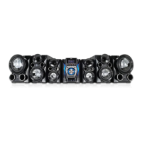
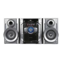
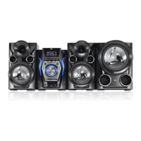
| Model | MCV903 |
| Category | Stereo System |
| Number of Discs | 1 |
| CD Player | Yes |
| USB Port | Yes |
| FM Radio | Yes |
| Playable Media | CD |