EasyManua.ls Logo

LG Multi-Inverter - Page 34

LG Multi-Inverter
123 pages
To Next Page IconTo Next Page
To Previous Page IconTo Previous Page
Loading...
- 33 -
Copyright ©2007 LG Electronics. Inc. All right reserved.
Only for training and service purposes
LGE Internal Use Only
Part 2 Functions & Controls
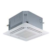
6.7.3 Group Control(Optional Wiring)
You can use a group control operation after connecting the brown and yellow wire of each air-conditioner.
Remove the resistor "OP 7" in remote controller.
It operates maximum 16 Units by only one Wired Remote Controller,
and each Unit starts sequentially to prevent overcurrent.
Wiring design
Features
Use Only One Wired Remote Controller with several air conditioners(max. 16 Units)
Random starting to prevent overcurrent.
Operation unit
ZONE
1234
Humidify
JET
AUTO
AUTO SWING OPERATION
FAN SPEED
Program set
SUB FUNCTION
SET TEMP
Room Temp
HI
MED
LO
Heater
Defrost
Filter
Preheat
Out door
Time
Timer
On
Set no. Time
Off
01 03 05 07 09 11 13 15 17 19 21 23
Indoor Unit 1
Terminal(Local Supply)
Block
Terminal(Local Supply)
Block
Terminal(Local Supply)
Block
Main PCB
#1
Main PCB
#2
Main PCB
#16
Wired Remote Controller
Slide Switch
OP7
Remote
Controller
PCB
Indoor Unit 2
Main PCB
Indoor Unit 16
Connector
RED(12V)
YL(SIGNAL)
BR(GND)
RED(12V)
YL(SIGNAL)
BR(GND)
YL(SIGNAL)
BR(GND)
YL(SIGNAL)
BR(GND)
YL(SIGNAL)
BR(GND)
YL(SIGNAL)
BR(GND)
Connecting Cable(Local Supply)
Connector Connector
....
....
Be careful not to exchange the color of wires.
The maximum length of connecting wire should be below 200m(25) on connect-
ing each units.
Use a wire more than 0.5mm2

Related product manuals