45
Installation Manual
Due to our policy of continuous product innovation, some specifications may change without notification.
©LG Electronics U.S.A., Inc., Englewood Cliffs, NJ. All rights reserved. “LG” is a registered trademark of LG Corp.
E
Insulated Duct
Clamp
Seal with Insulation
Label Component
Factory Supplied (Purchased Separately)
1 Indoor Unit
Field Supplied
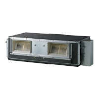
2 Duct Chamber (Sub-Duct)
3Duct
4 Vent
5 Air Outlet Insulation
Duct Chamber (Sub-Duct) (2)
Connection between indoor unit and insulated flexible duct.
The duct chamber should be covered by insulation. Thickness of
the insulation should be more than 3-15/16 inches (10 mm) on the
outside, and 3/16 inches (5 mm). on the inside. If the insulation is
not thick enough, condensation will form on the duct chamber (sub-
duct).
Duct (3)
Recommended duct diameter is Ø 7-7/8 inches (Ø200 mm).
The duct should be an insulated flexible duct, or insulation should be
installed.
Air Outlet Insulation (5)
Seal the air outlet of the side where the branch duct is installed.
The air outlet should be completed sealed to prevent air flow from
decreasing.
• ,IWKHLQVXODWLRQRQLQWKHGXFWFKDPEHUVXEGXFWLVQRWWKLFN
HQRXJKFRQGHQVDWLRQZLOOIRUPRQLQWKHFDELQHW
• ,IWKHLQVXODWLRQRQWKHDLURXWOHWLVQRWWKLFNHQRXJKFRQGHQVDWLRQ
ZLOOIRUPRQWKHYDQHDQGIURQWSDQHO
• ,IWKHLQVXODWLRQRQWKHDLURXWOHWGRHVQRWFRYHULWHQWLUHO\FRQGHQ-
VDWLRQZLOOIRUPRQWKHYDQHDQGIURQWSDQHO
Ceiling
Panel
5. Install the insulated flexible duct. Use a clamp to secure so that no leaks from the connection occur.
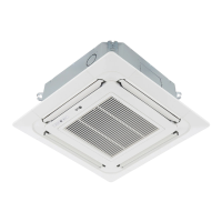
6. Remove the cassette indoor unit front panel, and install insulation to seal the air outlet on the branch duct side.
INSTALL BRANCH DUCT
Figure 45: Installing the Insulated Flexible Duct.
,IWKHDLURXWOHWLVQRWVHDOHGSURSHUO\WKHEUDQFKGXFWDLUÀRZZLOOGHFUHDVH
Figure 46: Sealing the Air Outlet on the Branch Duct Side.
5HFRPPHQGHG$LU2XWOHW,QVXODWLRQ'LPHQVLRQ7KLFNQHVV
• 6HHGLDJUDPDWULJKWDQGLQIRUPDWLRQ
EHORZIRUUHFRPPHQGHGDLURXWOHW
LQVXODWLRQGLPHQVLRQV
( LQFKHV[LQFKHV
PP[PP
• 7LJKWO\LQVWDOOLQVXODWLRQWKDWFRYHUV
WKHHQWLUHDLURXWOHW
• 5HFRPPHQGHGLQVXODWLRQWKLFNQHVVLVPRUHWKDQLQFKHV
PP
,IWKHLQVXODWLRQWKLFNQHVVLVOHVVWKDQLQFKHVPPFRQGHQ-
VDWLRQZLOOIRUPRQWKHYDQHDQGIURQWSDQHO
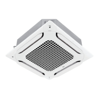
Figure 47: Cassette Indoor Unit Duct System Schematic.
Table 13: Cassette Indoor Unit Duct System Legend.