8
Multi V Ducted Indoor Units
Due to our policy of continuous product innovation, some specifications may change without notification.
©LG Electronics U.S.A., Inc., Englewood Cliffs, NJ. All rights reserved. “LG” is a registered trademark of LG Corp.
INTRODUCTION
Ducted Indoor Units
This manual describes how to install LG ducted indoor
units (IDU) for Multi V Variable Refrigerant Flow (VRF)
heat pump and heat recovery systems. Table 3 lists
the available models. Refer to LG’s Multi V Indoor
Unit Engineering Manual for complete detailed
engineering data and selection procedures.
Safety
Safety of personnel is the primary concern during all
procedures. Read and understand the safety sum-
mary at the front of this manual. Read and understand
this installation procedure before beginning installa-
tion. Use the appropriate tools and accessories during
installation. Plan your work and do not work alone, if
possible. Know how to obtain emergency medical and
fire fighting assistance.
• Pipes - vapor line and liquid line, with insulation
• 3/8” or 1/2” nuts, at washers, and lock/split
washers
• 3/8” or 1/2” threaded hanger rods
• Insulated drain hose
• Additional drain hose
• Connecting cable (power and control)
• Level
• JIS screwdriver
• Electrical lineman pliers
• Electric drill
• Holesaw
• Drill
• R410A aring tool set
• Tubing cutter
• Tube/pipe reamer
• Torque wrenches
• Allen wrench
• Refrigerant gas-leak detector
• Thermometer
Installation work must be performed by trained personnel and in accordance with national wiring
standards and all local or other applicable codes. Improper installation can result in re, electric
shock, physical injury, or death.
Note:
Please read all instructions before installing this product. Become familiar with the unit, its compo-
nents and connections, and the order of installation. Incorrect installation can degrade or prevent
proper operation.
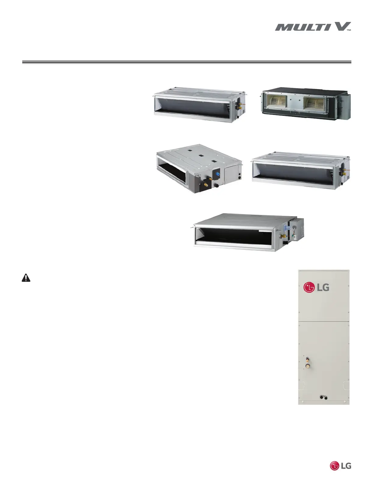
Figure 3: Convertible Mid Static Ducted,
MA Chassis
Required Tools (field provided)
Required Parts (field provided)
Figure 1: High Static Ducted, M2/M3 Chassis
Figure 4: Mid Static Ducted, M1/M2/M3
Chassis
Figure 2: High Static Ducted, B8
Chassis
Figure 5: Low Static Ducted, L1/L2/L3 Chassis
Figure 6: Vertical Air Handling Unit, NK/
NJ Chassis
Installation Personnel
This equipment is intended for installation by personnel trained
in the required construction, mechanical, electrical, and/or other
disciplines.
Applicable Codes
Personnel must be familiar with and follow the applicable national,
state, and/or local codes.



 To Next Page