A13
Standard Repair Process Detail Technical Manual
A13
③
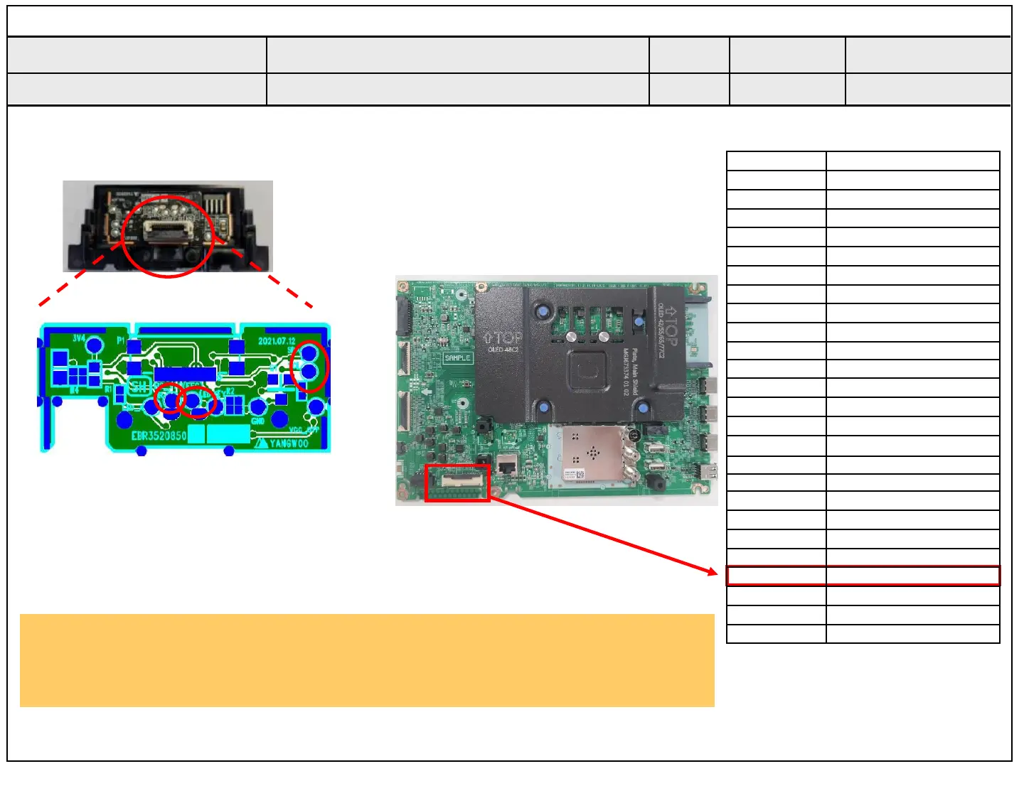
Pin Pin name
1 3.5V_WIFI
2 WIFI_DM
3 WIFI_DP
4 GND
5 WOL/WIFI_POWER_ON
6 3.5V_WIFI
7 WIFI_SUSPEND/RESUME
8 GND
9 COMBO_RESET
10 BT_WAKEUP_HOST
11 GND
12 3.5V_WIFI
13
N/C
14 N/C
15 N/C
16 EYE_SDA
17 EYE_SCL
18 GND
19 IR
20 LED_R
21 GND
22 +3.5V_ST
23 KEY2
24 WOV_PDM0_DATAIN
25 WOV_PDM_CLKOUT
1. Check IR cable condition between IR & Main board.(Check picture number① and ②.)
2. Check the Pin 22, Standby Power 3.5V. (③)
3. AS checking the Pre-Amp(IR LED light) , the power is in ON condition, an Analog
Tester needle should move slowly, otherwise, it’s defective.
Checking order to check remote control
Remote control operation checking method
D. Function error
Established
date
Revised
date
Error symptom
Content
① IR & EYE Sensor
55/65CS
Eye
LED
IR
②
 Loading...