MC860H High Performance Digital Stepper Driver MC860H High Performance Digital Stepper Driver
5 6
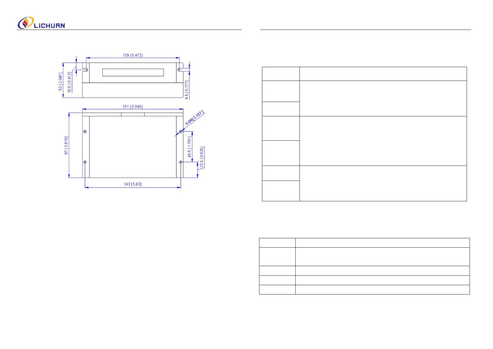
◆ Installation specifications (unit: mm [inch])
Figure 1: Installation specifications
◆ Elimination of Heat
·
Driver
’
s reliable working temperature should be <70
℃
(158
℉
), and motor working
temperature should be <80
℃
(176
℉
);
· It is recommended to use automatic idle-current mode, namely current automatically
reduce to 60% when motor stops, so as to reduce driver heating and motor heating;
·
It is recommended to mount the driver vertically to maximize heat sink area.
Use forced cooling method to cool the system if necessary.
3. External terminal instructions
◆ Control Signal Connector
Pulse signal: In single pulse (pulse/direction) mode, this input represents
pulse signal, each rising or falling edge active; 4-5V when PUL-HIGH,
0-0.5V when PUL-LOW. For reliable response, pulse width should be longer
than 1.5μs. Series connect resistors for current-limiting when +12V or
+24V used. The same as DIR and ENA signals.
DIR signal: In single-pulse mode, this signal has low/high voltage levels,
representing two directions of motor rotation; For reliable motion
response, DIR signal should be ahead of PUL signal by 5μs at least.
4-5V when DIR-HIGH, 0-0.5V when DIR-LOW. Please note that rotation
direction is also related to motor-driver wiring match. Exchanging the
connection of two wires for a coil to the driver will reverse motion
direction.
Enable signal: This signal is used for enabling/disabling the driver. High
level (NPN control signal, PNP and Differential control signals are on the
contrary, namely Low level for enabling.) for enabling the
driver and low level for disabling the driver. Usually left
UNCONNECTED (ENABLED).
Power supply, 24~90 VDC,18~80VAC, Including voltage fluctuation and EMF
voltage.
 Loading...