Installation Considerations
4
10. A breaker coordination study should be performed to ensure proper handling of fault currents.
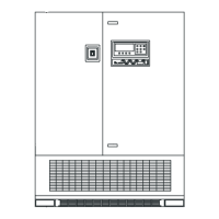
Figure 1 Multi-Module 100 to 225kVA UPS
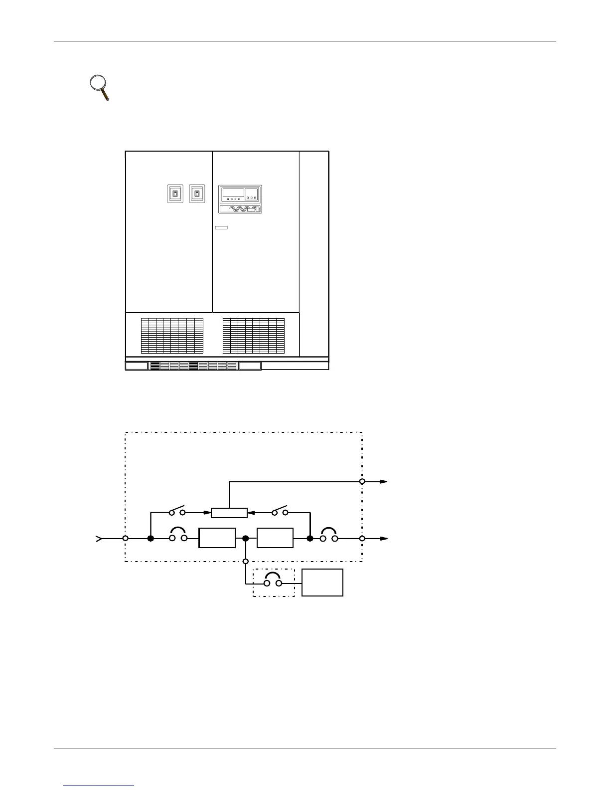
Figure 2 UPS Multi-Module Unit block diagram
NOTE
The instantaneous trip setting of the breaker feeding the SCC bypass input should be high
enough to accommodate short-duration overloads. The bypass static switch inside the SCC can
draw up to 10 times the system’s rated current for up to three cycles.
100-225kVA, bottom-entry
CB1 Module Input Breaker
CB2 Module Output Breaker
MBD Module Battery Disconnect
CB2
Rectifier/
Charger
Controls
CB1
CONTROL POWER
UPS MODULE
Inverter
MBD
Utility
Input
Power
Control
Wiring
To SC C
Battery
Output
Power
To SC C
 Loading...